- Begin laying out a pipe run as explained in Drawing a Pipe Run.
- On the Properties palette, under General, specify a gravity-based routing preference.
- Specify a nominal size for the pipe segment.
- Under Routing, for Slope format, select a format from the list.
For example, selecting Rise/Run with Fractional Rise sets a fractional slope per foot (for example, 1/4” per foot).
Tip: Slope format is also available on the General tab of the Pipe Layout Preferences dialog box. - For Slope, enter a value based on the current slope format. Tip: A negative slope value pitches the pipe downward from the main or branch in the isometric view. For example, -1/4” reflects a downward 1/4” per foot slope.
- Expand Advanced, and under Routing Options, for Use Fitting tolerance, select Yes.
Fitting tolerance refers to the angle of deflection that is allowed on a fitting connection. Yes (default) turns on angle of deflection for fittings that support sloped pipe runs.
Tip: If a female fitting, such as a flange, does not support angle of deflection, the software disregards a Yes selection. - For Joint direction, specify an orientation.
Joint direction controls the orientation of male-female connections for routing preferences that support male-female fittings.
Tip: If you are drawing pipe in the direction of the flow, choose Male into Female (default). If you are drawing against the flow, choose Female out to Male. - For Branch fitting, specify a combination. For example, Tee or Wye (Lateral) specifies that the software will first attempt to add a tee to the branch. Otherwise, the software will add a wye (lateral).
- Under General, for Routing, select a branch angle.
Selections for branch angle vary depending on the values that are defined in the catalog content. The selected angle determines how the branch will be drawn. Select Values from catalog selection to use all angles in the current routing preference in the layout.
If the desired angle in the layout is outside the range of the standard angle and tolerance, the Choose a Part dialog box prompts you to make a part substitution.
- Specify additional points in the pipe run. Note: The software displays the slope value for the pipe segment in the pipe run.
- (Optional) Click
 (Preferences) to make connection assignments on fittings in your drawing in the Pipe Layout Preferences dialog box.
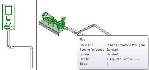
The following example shows sloped piping in plan versus SW Isometric views.
As you continue to lay out parts and connect pipe objects in the run, auto layout can generate routing solutions. The command line prompts you to accept the preferred solution.
The software inserts a coupling or an elbow into the piping layout, depending on the allowable fitting tolerance. For example, you might draw pipe at an angle of 5 degrees. Then, if the layout angle is less than the allowable fitting tolerance of 10 degrees, a coupling is inserted into the layout. However, if the layout angle is greater than the allowable fitting tolerance, the software inserts an elbow.