After attaching a referenced drawing (xref) of the architectural plan to your drawing, typically you continue by placing panels or devices in the layout.
To start drawing with a specific style of panel, in the Styles Browser
When you add a panel, you can create one or more circuits assigned to the panel at the same time. Alternatively, you can use Circuit Manager to create the circuits before or after you add panels or devices.
To add panels
Insert the panels
- Start the add command by doing one of the following:
- Click
 .
.

- Open the Panel tool palette, and select a tool.
If necessary, scroll to display the tool. Because tools contain pre-configured properties for the objects they create, you might not need to specify some of the panel properties referenced in this procedure.
- Enter PANELADD.
Note: On the Properties palette, indicates a property is available only when you are adding panels, not when you are modifying them.
- Click
- Specify or change the properties of the panel or change the panel to add by changing the panel style. To change the style, in the Properties palette Basic General Style click on the image. The Styles Browser palette loads with Object Type Panel.
If you want to search for a style... Then in the Styles Browser palette… in the current drawing select the Drawing File as Current Drawing. Pick a style from the gallery and click
 to select it.
in all open drawings set the Drawing Source to Currently Open Drawings and the Drawing File to All Drawings. Pick a style from the gallery and click
to select it.
in all open drawings except the current drawing set the Drawing Source to Currently Open Drawings and the Drawing File to All Without Current Drawing. Pick a style from the gallery and click
to select it.
in Content Library Drawings set the Drawing Source to Content Library Drawings and choose an appropriate file from the Drawing File drop-down. Pick a style from the gallery and click
to select it.
in a drawing in the directory specified as the default content location for electrical panels or a drawing template set the Drawing Source to Content Library Drawings and the Drawing File to Manage Content Library. In the Content Drawings Library dialog box, add a folder or a drawing containing the styles. - For Description, enter a description of the panel.
- Expand Location, and for Align to objects, specify how you want to align the panel:
If you want to… Then… snap to an object using object snaps and have the software align the panel perpendicular to the object select Yes. The software can align the panel perpendicular to a wall, space boundary, line, polyline, spline, arc, or circle in the current drawing or in an xref. manually align the panel select No. Note: If you select Yes for Align to objects, the software inserts the panel using the insertion point of the underlying block and rotates it as needed to align it perpendicular to the object to which you snap. As a result, you cannot specify a value for Justification on the Properties palette, or a value for Rotation on the command line. - For Justification, select the point on the panel to use as the insertion point.
You can select either the insertion point of the view block that represents the panel, or one of 9 other points on the panel, such as Top Left or Middle Center.
- Specify an elevation by doing one of the following:
- For Preset Elevation, select a defined elevation.
- For Elevation, enter an elevation.
The difference in the elevation of the devices, the wires, and the panel for a circuit is used to calculate the circuit length. Note that the circuit length can only be calculated if the panel and all of the devices on the circuit are in the current drawing.
- In Advanced System and for System, select the system to which the panel belongs. If you want to change the System Definition, or search for a System Definition, click on the
 . The Styles Browser palette opens with the Object Type Electrical System Definitions.
If you want to search for a system... Then in the Styles Browser palette… in the current drawing select the Drawing File as Current Drawing. Pick a style from the gallery and click
to select it.
in all open drawings set the Drawing Source to Currently Open Drawings and the Drawing File to All Drawings. Pick a style from the gallery and click
to select it.
in all open drawings except the current drawing set the Drawing Source to Currently Open Drawings and the Drawing File to All Without Current Drawing. Pick a style from the gallery and click
to select it.
in Content Library Drawings set the Drawing Source to Content Library Drawings and choose an appropriate file from the Drawing File drop-down. Pick a style from the gallery and click
to select it.
in a drawing in the directory specified as the default content location for electrical panels or a drawing template set the Drawing Source to Content Library Drawings and the Drawing File to Manage Content Library. In the Content Drawings Library dialog box, add a folder or a drawing containing the styles. - In Design Data Name, enter a unique name for the panel.
- For Rating, enter a panel rating.
- For Voltage phase-to-neutral, select from the drop-down list. The voltage list comes from the Electrical Preferences - Voltage Definitions.
- For Voltage phase-to-phase, select from the drop-down list. The voltage list comes from the Electrical Preferences - Voltage Definitions.
- For Phases, select the number of phases: 1or 3.
- For Wires, select the number of wires: 3 or 4.
- For Main type, select Main lugs only (MLO) or Main circuit breaker (MCB).
- For Main size (amps), enter the main size.
- For Design capacity, enter the design capacity.
- For Panel type, select ANSI or ISO.
- For Enclosure type, enter an enclosure type.
- For Mounting, select Surface, Recessed, or Floor.
- For AIC rating, enter a rating.
- For Fed from, enter the fed from information.
- For Notes, enter any notes.
- If you do not want to create circuits, skip this section and proceed to the section on inserting the panel. Otherwise, expand Circuits, and for Create circuits, select Yes.
- Beside Circuit Settings, click


- On the Circuit Settings worksheet, for System Type, select the system type of the circuits: Power and Lighting, General, or Other.
Note: If you select Power and Lighting or Other for the system type, the connectors on the electrical objects in your drawing must have the same system type in order to be placed on the circuit. To allow devices of any system type to be connected to the circuit, select General for the system type. The General system type allows objects of different system types to connect. For more information, see Circuits.
- For System, select an electrical system for the circuits.
- Specify additional circuit properties, which vary according to the system type of the circuit:
If the system type is… then… Power and Lighting Do the following: - Enter the total number of slots on the panel.
- Enter the number of 1-pole, 2-pole, and 3-pole circuits to create. You can only create 3-pole circuits if you selected 3 for Phases on the Properties palette.
- For each type of circuit to create (1-pole, 2-pole, and 3-pole), select a voltage. You can select from the voltages defined in the drawing that are valid for the number of poles.
Note: If the number of 1-pole, 2-pole, and 3-pole circuits is less than the number of slots, the remaining circuits will be created with a rating of 0.
General or Other for Number of circuits, enter the number of circuits to create. - For Circuit Description, specify the description for circuits with breakers and circuits without breakers that will display in the Circuit Manager when new circuits are created.
- In the drawing, insert the panels as follows:
If, for Align to objects, you selected… then… Yes use object snaps to snap to an object (such as a wall) at the desired insertion point, and click to insert the panel. Note: If you have difficulty snapping and aligning to an object, zoom to the area or modify the size of the AutoSnap aperture as needed. The aperture size determines how close to a snap point you can be before the magnet locks the aperture box to the snap point. You can modify the size on the Drafting tab of the Options dialog box.No do the following: - Click to specify the insertion point.
- Rotate the panel by moving the cursor or entering the number of degrees on the command line, and click to insert the panel. Alternatively, you can press Enter to accept the default rotation, and then click.
- Repeat the previous step to add additional panels with same properties.
- On the Properties palette, modify the panel properties and then insert additional panels, or press Enter to end the command.
- If you do not want to link this panel to an existing panel, skip this section. Otherwise, select the panel, right-click and click Connect To.
- Select the panel you want to connect to and click OK.
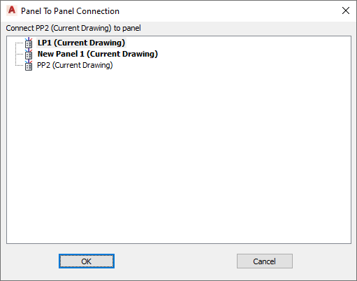 Note: Valid connections are shown in bold.
 - Select the method to use when connecting the panels and click OK.
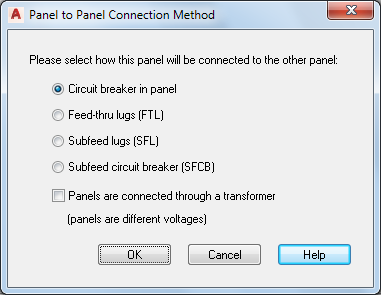
If you select… then… Circuit breaker in panel the panel is added as a subfed panel to an existing circuit in the linked panel. Feed-thru lugs the panel is added as a subfed panel to a feed-thru lug in the linked panel. Subfeed lugs the panel will be added as a subfed panel to a subfeed lug circuit in the linked panel. Subfeed breaker the panel will be added as a subfeed panel to a subfeed breaker circuit in the linked panel. Panels are connected through a transformer (panels are different voltages) the panel will be connected through a transformer when panels are of different voltages. Note: To remove the link to a panel, select the panel, click
.

Specify general properties
Specify location properties
Specify advanced properties
Optionally create one or more circuits for the panel
Optionally link the panel to an existing panel