You can draw cable tray and conduit runs in order to form complete electrical networks.
In the software, a run is the cable tray or conduit parts that encase or support wires, bringing them from one point, such as a junction box or a panel, to another point, such as the junction with another run. A network is a group of interconnected cable tray or conduit runs.
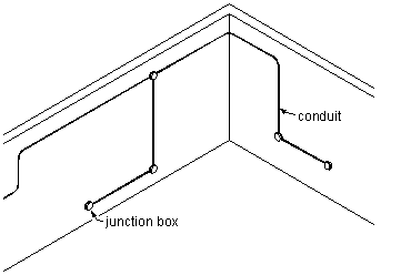
Viewing conduit and junction boxes in 3D
To add cable trays and conduits to a drawing, you draw the main runs, locating the risers. As you draw cable tray or conduit runs, you lay out wireway geometry by specifying points in the drawing. The software automatically adds fittings to connect segments when forming a run and to connect runs to risers and branches when forming a network (auto layout). You can also add fittings manually.
You can control which parts are inserted by configuring layout preferences before you begin drawing your wireway runs.
A cable tray or conduit run is made up of individually drawn segments. You draw a segment by specifying its properties, and then specifying points in the drawing.
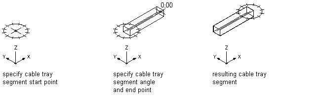
Drawing a cable tray segment
Once you have drawn the cable tray or conduit runs, you can connect them to form a complete cable tray or conduit network. AutoCAD MEP 2022 toolset snaps can help you locate valid connection points on objects in your drawing. You can start a run at the end of a segment or run, or at any point along the path of another run. In this case, the software inserts an appropriate fitting to connect the 2 runs, creating a branch.

Drawing a branch
Cable tray and conduit components store properties such as connection type, size, system, and part type. When you connect to existing cable tray or conduit runs to create branches, part properties are inherited, providing a consistent method of drafting a layout. This ensures that you are creating intelligent building system designs.
You can also assign systems to cable tray and conduit to enable layouts to act together by maintaining the same look and feel throughout the system. For example, a group of cable tray runs can represent a power and lighting system, while another group of cable tray runs can represent a general system.
Finally you can add a schedule that contains the tagged parts for conduit and fittings in a drawing.