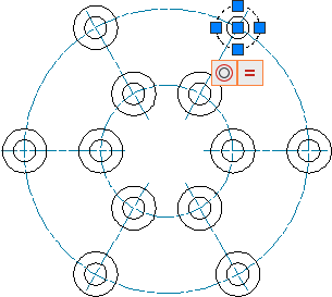
When you create centerlines, the program assigns them colors and line types automatically, and by default, places them on layer AM_7.
Centerline
Using AMCENTLINE, you can draw a centerline by defining its starting points and endpoints. When you select a starting point and an endpoint on contour edges, the centerlines extend beyond the selected edges. You can specify the extension value in the Centerline Settings dialog box, which is accessed via the AM:Standards tab of the Options dialog box.
You can either click points in the drawing window or you can enter coordinates to specify a starting point and an endpoint.
Centerline cross
Using AMCENCROSS, you can draw a centerline cross by defining its center point.
The program always draws a centerline cross from a center point and extends it outward, ensuring that no blank space appears where the centerlines cross.
You can either use the pointing device to click points in the drawing window or you can enter coordinates to specify an insertion point and a diameter.
To draw a centerline cross with another angle alignment in the drawing, change the UCS to that angle before starting this command.
Centerline cross with a hole
The AMCENCRHOLE command works the same way as the Centerline Cross command, except that it requires a value for the diameter of the hole. The size of the cross is automatically adjusted to match the size of the hole.
You can either use the pointing device to click points in the drawing window or you can enter coordinates to specify an insertion point and a hole diameter.
To create a centerline cross with more than one hole, enter the pipe symbol | between the diameter values.
After selecting the diameter, use the pointing device to insert additional centerline crosses with holes of the same size.
The diameter value you enter becomes the default diameter value.
Centerline cross in a corner
The AMCENCRCORNER command creates a hole at a preset offset from each side of a corner.
You can either use the pointing device to click points in the drawing window or you can enter coordinates to specify the offset of the hole's center cross from the first and second contour lines. You can specify the diameter size for the hole, specify a standard or custom content, or specify no hole, which draws just the cross.
To create concentric holes, enter multiple diameter values. Enter the pipe symbol | between the values. The Standard Part option enables you to place a standard hole or a screw connection at the selected location.
The diameter value you enter becomes the default diameter value.
Centerline cross on a plate
The AMCENCRPLATE command creates centerline crosses with holes at every corner of a plate and places those holes either in or around the plate.
You can either use the pointing device to click points in the drawing window or you can enter coordinates to specify the offset distance between the contour edge and the hole. You can specify the diameter for the hole, specify a standard or custom content, or specify no hole, which draws just the cross.
The diameter value you enter becomes the default diameter value.
Centerline cross on full circle
The AMCENCRFULLCIRCLE command draws and evenly distributes circles with a centerline cross. Depending on the number of elements you draw on the periphery of the circle, the program creates radial centerlines and distributes them evenly in the circle.
To draw concentric holes, enter multiple diameter values separated by the pipe symbol |.
The diameter value you enter becomes the default diameter value.

Centerline cross with an angle
The AMCENCRANGLE command works the same way as the AMCENCRFULLCIRCLE command, except that you can place the radial centerlines at any angle on the circle periphery. You can also place holes or standard or custom content at the intersection point between the circle periphery and the radial centerlines.
The diameter value you enter becomes the default diameter value.
Centerline cross in a hole
The AMCENCRINHOLE function enables you to insert centerline crosses into existing holes. The program creates a centerline cross and displays it in the selected hole. It adapts the size of the cross to the diameter of the hole.
The diameter value you enter becomes the default diameter value.
Centerline between two lines
The AMCENINBET command enables you to create a centerline between two existing lines that you want to mark as symmetrical in your drawing. The length of the centerline is based on the length of the line you select first. You can also use this command to bisect the angle between two non-parallel lines.