In this exercise you convert a grayscale image to bitonal (black and white) images and clean up the converted image:
- Threshold converts a grayscale image of a soils map to a bitonal image.
- Invert reverses light and dark areas of the image to improve readability. In the case of bitonal images, it also has the effect of reversing background and foreground colors.
- Despeckle removes undesired spots and speckles from the image.
By converting the grayscale image to a bitonal (black and white) image, inverting the image, and removing speckles, you make the soil boundaries in the image easier to identify. The resulting map can be readily converted to vector using the AutoCAD Raster Design toolset Vectorization Tools.
In this lesson, you also export the modified image with a world correlation file.
Related Exercises
- Exercise S3: Cleaning Up Images with Invert and Mirror
- Exercise V1: Setting Options and Creating Basic Vector Objects
Before doing this exercise, ensure that AutoCAD Raster Design toolset options are set as described in the exercise Exercise A1: Setting AutoCAD Raster Design Toolset Options.
Exercise
- In the \Tutorial5 folder, open the drawing file Map_06.dwg. In the next few steps, you will change the background color of the Model space to black.
- At the Command line, enter the OPTIONS command to open the Options dialog box.
- Click the Display tab.
- Click the Colors button. The Drawing Window Colors dialog box opens.
- In the Interface Element list, select Uniform Background.
- In the Color list, select Black.
- Click
Apply & Close in the
Drawing Window Colors dialog box, then click
OK in the
Options dialog box.
Convert the grayscale image to bitonal
- Click
Raster menu
 Image Processing
 Histogram. Press Enter to edit the entire image. The
Histogram dialog box is displayed.
On the Threshold tab, use the slider to determine which pixels will be black and which will be white after you convert the image. The shades of gray to the left of the slider become black, and those to the right become white.
- Move the slider to 82, observing the effect on the image in the preview window.
This exercise uses one image. However, if you select multiple images, you can select the image name below the preview to observe the effect of the threshold value on that image. The selected images convert to black and white when you click Apply and Close.
- Click
Apply and Close to convert the image.
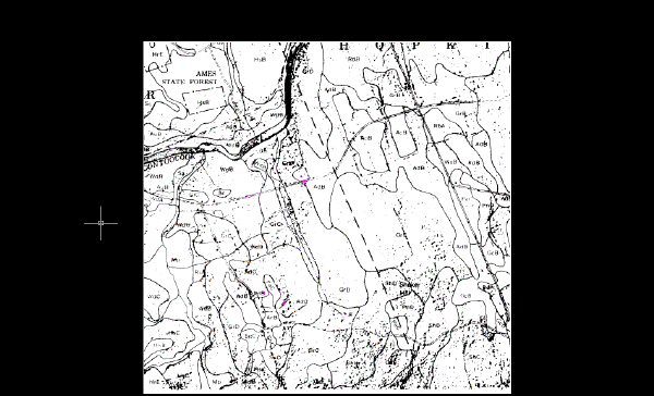
The following example shows how the image of the soils map should appear after you convert it to a bitonal (black and white) image. The image has a light background and dark line work that is difficult to read. The image also contains large speckles.

Export the image
- Click
Raster menu
 Export
 Image.
- In the Export dialog box, enter Soilsmap_world_03.cal for the filename, select CALS1 for the file type, and click Export.
- In the Export Options dialog box, select Maintain Drawing Link to Image and under Correlation, select World File.
- Click
Finish.
Invert the image
- Click
Raster menu
 Cleanup
 Invert.
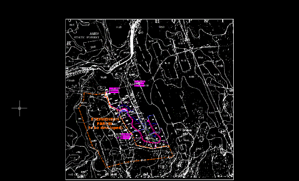
The following example shows how the image of the soils map should appear after you invert the light and dark areas of the image. The image still contains many large speckles.

Remove speckles from the image
- Under Insert Options, select the Insertion Dialog option. Also make sure that Show Frames Only and Zoom To Image(s) boxes are cleared.
- Click
Open to display the
Image Correlation dialog box. Select the
Source tab.
You are prompted to continue or to respecify the pixel size.
- Click the
Insertion tab and click
OK.
The pixels about to be removed are highlighted. In a real project, this is when you can zoom in to inspect the image and ensure that essential data is not highlighted for removal. You can specify pixels to exclude from the removal set in a variety of ways.
- Press Enter to remove the highlighted speckles.
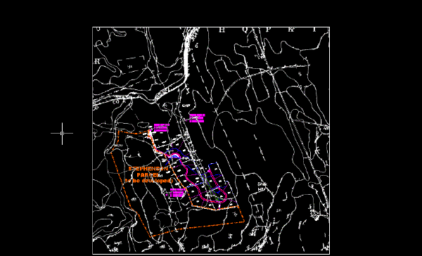
The following example shows how the image of the soils map should appear after you remove the speckles.

- Close the drawing without saving changes.