Use the FeatureCAM To VERICUT dialog to specify the options for exporting milling or turn/mill documents as Vericut projects:
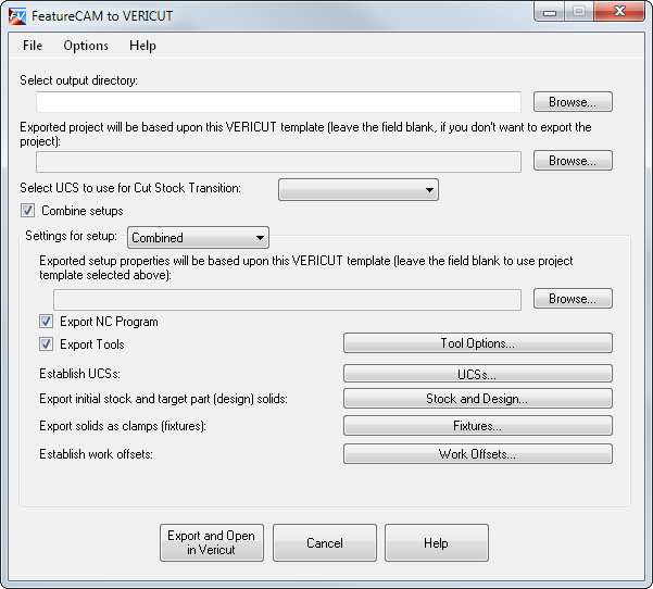
Select output directory — Enter the path of the folder in which you want to save the project, or click Browse to select it.
Exported project will be based upon this VERICUT template — Click Browse and select a .VcProject file to use as the Vericut template. The information is loaded from the template into the add-in, such as the Attach components and the machine subsystems. You must select a Vericut template before defining the export settings.
Select UCS to use for Cut Stock Transition — If the part must be moved between setups during simulation, select a UCS from the list to describe the movement.
Combine setups — Select this option to combine multiple setups into one. You must select this option for 5-Axis parts.
Settings for setup — Select the setup for which you want to edit the settings. Edit the settings for each setup you want to export.
Exported setup properties will be based upon this VERICUT template — To specify a separate Vericut template for each setup, click Browse and select a template file to use for the selected setup. You can use this if you are using a different machine for each setup. This does not affect the global project settings.
Export NC Program — Select this option to generate and export the NC program with the document. If this is deselected, VERICUT uses the NC program specified in the template, or you can specify the NC program manually in VERICUT.
Export Tools — Select this option to export information for all the tools used in the document. If this is deselected, VERICUT uses the tools specified in the template, or you can specify them manually in VERICUT. Click Tool Options to display the Tool Export Options dialog, which you can use to specify the options for identifying tools in VERICUT.
Establish UCS — Click UCSs to display the UCSs dialog, which you can use to specify attach UCSs and Attach components.
Export initial stock and target part (design) solids — Select Stock and Design to display the Stock and Design Export Settings dialog, which you can use to specify options for exporting the stock and part solids.
Export solids as clamps (fixtures) — Click Fixtures to display the Fixture Export Options dialog, which you can use to specify the clamps and fixtures to export.
Establish work offsets — Click Work Offsets to display the Add Work Offset dialog, which you can use to specify VERICUT work G code offsets.
Machine turret information — Click this button to display the Machine Turret Info dialog, which you can use to specify the turret options. This is only available for multi-turret parts.