The Boss feature removes all material between the boss curve and the stock boundary.
|
|
|
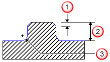
 Chamfer
 Height
 Bottom radius
To create multiple bosses on a surface, use multiple curves to create one boss feature only. This prevents the toolpaths from overlapping with each other, and enables you to specify the material you want to remain unmachined. None of the boss curves should intersect or contain each other. When building multiple bosses at the same height in the part, include all of the boss curves in the same Boss feature.
Boss features remove material all the way to the stock boundary, including any other features you may have placed above the boss shoulder height. To limit the area milled away by the Boss feature, use a stock curve, or set the Total Stock attribute.
If you use a stock model, the toolpaths are trimmed to the stock to prevent air cutting.
FeatureCAM follows this general process to create a Boss feature:
- Conducts an analysis of the curve and, using tool diameter and length as the selection criteria, determines the tool to use.
- For tool diameter, FeatureCAM analyzes the curve that defines the Boss and selects the largest tool that can cut the boss without gouging. (see Tool % of arc radius).
- For tool length, FeatureCAM picks a tool that has flutes long enough to cut to the bottom of the Boss height.
- If a tool that meets the criteria cannot be found, an error is displayed and NC code is not generated.
Endmills are automatically selected for the roughing and finishing passes, but you can override the automatically selected tool to specify a face mill.
- Chooses feeds and speeds using the Feed/Speed database that you can customize. Feeds and speeds are determined based upon the stock material.
- Performs a roughing pass, possibly in multiple Z steps based on the height of the Boss.
The important aspects of roughing are:
-
Getting to depth — The tool must get to depth, and this can be accomplished by a zigzag in Z (the default setting and influenced by
Max ramp angle), by plunging, or by pre-drilling (see
Pre-drill diameter and
Pre-drill point).
- Vertical step — The rough pass can have vertical steps with cut depth not more than 100% of the tool radius (see Rough depth and Rough pass Z increment).
- Horizontal stepover — FeatureCAM moves over laterally a percentage of the tool diameter (controlled with Rough pass %), as it steps across the feature.
- Finish allowance — The rough pass contains a Finish allowance attribute which controls how much material to leave for the finishing pass. By default this is 0.02.
- Performs a finishing pass. By default, the bottom is not finished. The roughing tool removes all of the material in Z. This is controlled by
Finish bottom, which finishes the bottom of a feature with a flat endmill up to the beginning of any bottom radius if present.
The important aspects of finishing are:
-
Tool selection — After the roughing pass, the roughing tool is used to finish the boss.
Use Finish Tool commands
FeatureCAM to choose a separate finishing tool (that has the same characteristics unless you override them).
- Ramp on — The finish pass ramps into the material with an arc equal to a percentage of the tool diameter (see Ramp diameter).
- Finish passes and overlap — The tool goes around the boss a number of times set by Finish passes, and overlaps the starting point by an amount controlled by Finish overlap.
- Ramp off — Uses another arc of the same size as the ramp on to move the tool away from the finished wall.
- Retract — Removes the tool from the stock area and sets up for the next operation.
- To edit all instances of this type of feature in the current document, use the Machining Attributes dialog.
- To edit a single feature, use the Tools, Milling, Strategy, and Misc. tabs for the feature in the Feature Properties dialog.
You can edit this process in these places:
The tooling database also has a large impact on how a feature is machined, and the feed/speed database helps to determine the feeds and speeds used.
To create multi-height Boss features or islands in a Pocket feature with different heights:
- Create the curves for the Boss or island and translate it to its proper location in Z.
- Use this curve as a Boss curve or island curve for a pocket.
See also: