You can use the Axis Smoothing tab of the Surface Milling Properties dialog to specify axis smoothing on Surface Milling toolpaths.
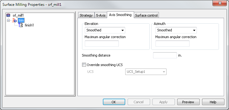
Elevation — Select how to smooth the elevation angle of the tool axis. An elevation of
 90
90 aligns the tool with the Z axis, and an elevation of 0 means the tool is in the XY plane.
Maximum angular correction — Enter the maximum angle the smoothed axis may deviate from the initial in the elevation direction. The maximum angular correction angle is only exceeded if the unsmoothed toolpath moves by more than this value in less than the Smoothing distance. In such regions, the angle may change by more than the Maximum angular correction to give a smooth result.
Azimuth — Select how to smooth the azimuth angle of the tool axis. Azimuth is the angle between the
 X axis and the projection of the tool in the XY plane.
Maximum angular correction — Enter the maximum angle the smoothed axis may deviate from the initial in the azimuth direction. The maximum angular correction angle is only exceeded if the unsmoothed toolpath moves by more than this value in less than the Smoothing distance. In such regions, the angle may change by more than the Maximum angular correction to give a smooth results.
Smoothing distance — Enter the distance over which to smooth the tool axis movement. When using Stepped on Surface, or with sudden changes in direction in the original toolpath (such as a right-angled corner), you get rapid changes of orientation of the tool axis which leaves dwell marks. To prevent this, the Smoothing distance blends the change in orientation and gives a much improved surface finish.
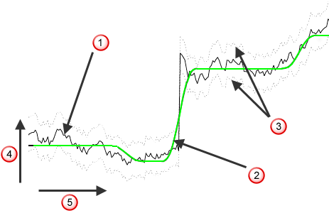
 Original toolpath, no smoothing
 Smoothed toolpath
 Maximum angular correction limits
 Azimuth or elevation
 Toolpath distance
Override smoothing UCS — Select this option to use a different UCS to the UCS used to generate the toolpath to define elevation and azimuth for smoothing.
UCS — Select the UCS to use when smoothing.
Stepped on surface example
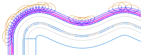
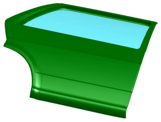
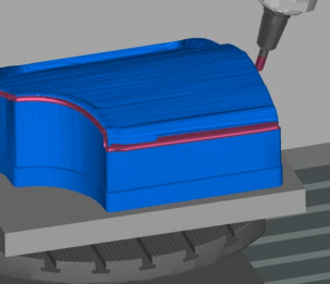
This car door part uses a trimming toolpath around the edge:
With no smoothing, the rotary table has a rocking motion and sudden direction changes can leave witness marks.
In some areas of the model, it is impossible to avoid the rotation, such as when the tool makes its way around the corners and the wheel arch. However, it is areas such as on this long edge of the door, where the machine table is rocking backwards and forwards, that you can avoid this using the Stepped on surface options:
|
|
|
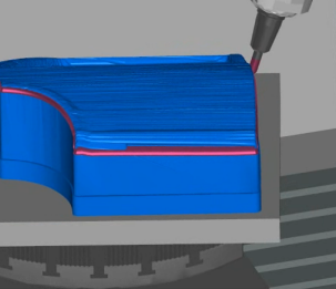
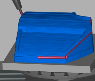
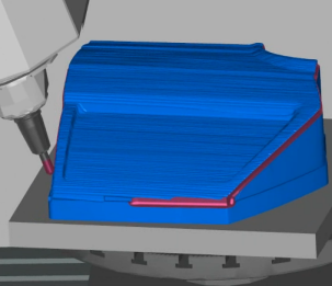
With Stepped on surface enabled for both Elevation and Azimuth, with a Max. angular correction of 80, the table does not rotate while cutting this area:
|
|
|
Stepped with links example
This example part uses the Pencil strategy to cut the bottom fillet:
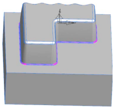
Enabling Stepped with links for both Elevation and Azimuth reduces the tool movement.
A centerline simulation shows the links that FeatureCAM inserts links so that it can change direction while not in contact with the surface: