Z rapid plane — Enter the minimum safe distance in Z above your part.
Before performing a rapid move away from a feature, the tool retracts to the Z rapid plane setting for that feature. The rapid move to the next feature changes in Z height, that is, changes Z coordinates, if the next feature has a different Z rapid plane setting. So that when it arrives at the next feature it is at the Z rapid plane for that next feature.
This value is relative to the top of your stock in the current user coordinate system. Compare with Plunge clearance.
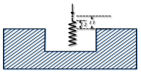
Plunge clearance — Enter the distance above the operation at which the tool feeds.
This is marked as L1 in the diagram.
For deep hole drilling, the drill retracts to this distance between pecks. For milling features, the default is to use the same value for roughing and finishing. As a result, the tool feeds from the top of a feature to the floor before cutting. To make the tool feed down into the feature, set the Plunge clearance for an operation to a negative value, but ensure the value is above the floor of the feature.
To rapid to depth, you can use a negative Plunge clearance, or select Relative plunge.
Z ramp clearance — Enter the distance above the operation at which ramping starts. Z ramp clearance is bound by Plunge clearance.
This is marked as L2 in the diagram.
Spline tolerance — This approximates the profile with arcs and lines if a profile is defined as a spline. The smaller the value of the parameter, the smoother the profile. This machining attribute is used in Feature Recognition to determine whether a surface is a Hole.
Posting tolerance — Enter the tolerance with which the toolpaths are created. Reduce the Posting tolerance value for small parts to create more precise toolpaths.
You must also adjust your post processor to output more digits. For example, if you adjust the posting tolerance from 0.001 to 0.0001, then you must adjust the digit format in the post processor so that the extra decimal place is used in the NC code. Reducing the posting tolerance creates additional lines of NC code, so you should only do this for high-precision NC machines that can use the high-precision coordinates, when required for an application.
Z index clearance — This is the clearance distance above the stock bounding cylinder.
Deburr radius — Enter a radius to automatically round sharp outside corners of the feature by the specified radius. The feature shape does not change, but the toolpaths are modified to reflect the rounding.
Min. corner radius — Enter a radius to automatically round the inside corners of a feature by the specified radius. The feature shape does not change, but the toolpaths are modified to reflect the rounding.
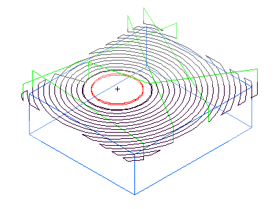
Min. rapid distance % — Enter the minimum distance, as a percentage of the tool diameter, that the tool can use a rapid move for. Moves smaller than this distance use a feed move.
Minimum rapid distance applies to 2.5D milling. Specify the value as a percentage of tool diameter.
This example shows a feature cut with a value of 400%:
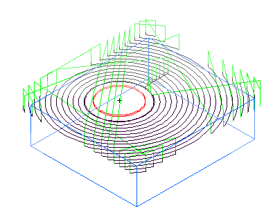
This is the same example with Min rapid distance set to 10% and the tool retracts and rapids between passes.
Back clearance — Used when machining a backbore Hole, Back clearance is the distance the backbore tool is from the bottom of the Hole when cutting the bore section.
Use edge-based stock curve finder — In certain cases, the Parasolid kernel does not compute a Stock curve correctly. If you have problems trying to compute a Stock curve from a Parasolid file, try selecting this option. This option is deselected by default because it is slower.
Speed % — This is a scaling factor for the spindle speeds generated by FeatureCAM. A value of less than 100 reduces the calculated speed rates. A value of more than 100 increases the rates.
Feed % — This is a scaling factor for the feeds generated by the system. A value of less than 100 reduces the calculated feed rates. A value of more than 100 increases the rates.
Plunge feed % — The percentage of the Feed % attribute to use during the initial plunge into the material. For example, if the Feed % attribute is 2000 MMPM and you set the Plunge feed % to 50, the resulting feed rate for the initial plunge is 1000 MMPM. See also First plunge feed %.
First plunge feed % — You can specify a slower feed rate for the first plunge move (the initial approach to the Stock) than for subsequent Z plunge moves to depth. This is a percentage of the Plunge feed %.
Feed unit — This changes the default feed rate units. Select the units that you want to be FeatureCAM's global feed rate units in the Feed unit menu:
|
Use IPM (inches per minute) Use IPR (inches per revolution) Use IPT (inches per tooth) |
Use MMPM (mm per minute) Use MMPR (mm per revolution) Use MMPT (mm per tooth) |
This global setting is reflected locally on the Feed/Speed page of the New Feature wizard and the F/S tab of the feature Properties dialog.
Use default feed unit in Operations List — When selected, the default feed unit is used in the Operations List.
Speed unit — Select the units that you want to be FeatureCAM's default speed units.
Use default speed unit in Operations List — When selected, the default feed unit is used in the Operations List.
Proportional plunge feed
If
Proportional plunge feed is selected, the feed rate of the ramping move is scaled based on the
Max ramp angle. Enter the maximum angle, in degrees, for ramping down to depth. It applies to helical or zigzag ramping. Set this value to
0 to cause a plunge cut. A
Ramp angle of
1 sets the feed rate of the plunging moves to approximately the milling feedrate. An angle of
90 sets the feed rate of the plunging moves to the value determined by
Plunge feed override %.
sets the feed rate of the plunging moves to approximately the milling feedrate. An angle of
90 sets the feed rate of the plunging moves to the value determined by
Plunge feed override %.
If Proportional plunge feed is deselected, then the feed rate of plunging moves is determined by Plunge feed override % regardless of the ramp angle.
Peripheral Feed dialog.