Creates a toolpath by rotating the job around the index axis. This axis is often the Z-axis in a turn/mill document and often the X-axis in a milling document. Rotary milling creates toolpaths that cut surfaces without the need for
wrapping. In a turn/mill document, the feature must have the
Cut with X-tool option selected in the
Tool Axis tab before you can create a rotary operation. The angle of the X-tool must also be 0 .
.
You can control four axis rotary milling with the following settings.
Strategy options
These attributes are available on the Strategy page of the New Feature wizard and the Strategy tab in the Feature Properties dialog.
Select a cutting style from:
-
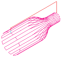
Linear
Linear rotary milling causes the tool to traverse along the index axis in straight lines, with the rotary axis only used at the end of each pass to reposition the job.
-
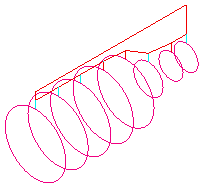
Circular
In circular milling the job rotates with the tool at a fixed position, effectively machining a circle. The tool then steps over the required amount and machines the next circle.
-
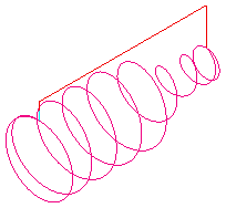
Spiral
A continuous spiral is cut along the length of the job when spiral milling is used. To ensure a clean finish a full circle is cut at the two ends. Because rotation is continuous, only Climb and Conventional milling are available (so, you must have a rotary head that can make an unlimited number of rotations).
Y offset is a distance to avoid cutting on the center of the tool.
Milling options
These attributes are available on the Milling tab in the Feature Properties dialog.
Angle start/end — Enter the angular positions where you want machining to start and end. It applies only to Linear or Circular milling. The angular limits are measured in a counter-clockwise direction when viewed along the positive Z axis. The area machined is between the start and end angles.
Index start/end coord — To limit the cutting area along the index axis, set Index start coord and Index end coord. For a turn/mill document these parameters control the extents of the toolpaths along the Z axis. For a 4-axis milling document, they are values along the index axis.
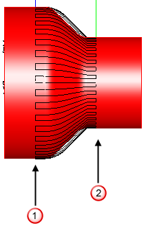
 Index start coord
 Index end coord
Stepover — For Circular milling, enter the distance between circular cuts. For Spiral milling, enter the distance the tool travels in a full revolution along the index axis.
Stepover angle — For Linear milling, enter the distance between the linear cuts as an angle around the index axis.