You can perform automatic 3D tracking based on the camera properties of the device used to acquire the image sequence you want to track. You can specify these properties, or let the analyzer automatically detect the best solutions for the analysis. Even if you want to perform object tracking on specific moving areas of the scene, you also start with an analysis using camera tracking to create a properly tracked camera.
To create a 3D camera track:
- Add an Analyzer Mono or Analyzer Stereo node, as explained in Adding an Analyzer Node.
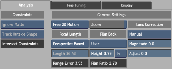
- In the Camera Tracking menu, set Analysis options. For example, decide if you need to use a matte or GMask in the analysis. In an image sequence of a busy street, you can create a matte or mask of moving elements (such as cars and people) to isolate this area from the analysis. See
Analysis Settings for details of each Lens Correction, Constraints, and Camera setting.
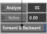
- Enable Forward & Backward to track the image sequence backward after the forward tracking has completed. This option takes longer, but you may get better results.
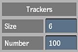
- If needed, adjust the size and number of trackers.
Smaller trackers can speed up the calculation, while larger trackers make the analysis more robust with regard to image noise and variations. A general rule is to increase the size of the trackers when tracking high-resolution footage (2K or larger) that contains more noise.
- Click Analyze.
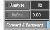
You can see a progress indicator beside the Analyze button. You can interrupt the analysis and resume it by clicking Analyze again.
Most of the time, tracking occurs in the background, allowing you to continue working while tracking. In Batch or Batch FX, you can use connected input and matte clips as the media to be tracked. In this case, tracking becomes a foreground process.
After tracking has completed and you press Confirm, the Analyze button changes to Update, and you can see the 2D tracks (the blue squares in the following example) and 3D points (green crosses) in your image, provided that you are in Analyzer 3D view.
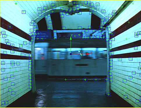
Image courtesy of Behavior Communications Inc.
The 3D camera connected to the analyzer node synchronizes to the results of your 3D tracking, and any further changes you make to the 3D track are reflected in this camera.
- If you are satisfied with the results of the tracking analysis, proceed to
Converting the Camera Analyzer Results. If you want to tweak your track results, see
Fine Tuning the Analysis.
Note: As a general rule, a Refine field value between 1 and 1.5 is considered a good quality track.
Set the focal length by adjusting the perspective grid
The tracking analysis algorithm can make a best estimate of the focal length for the camera without any user input (see Analysis Settings). In order to refine the algorithm's analysis you can use a perspective-based grid to define the focal length. The focal length determined through the perspective grid is then used as part of the analysis. If you do not use this perspective grid or manually enter a value for the focal length, the algorithm guesses at an estimate of the focal length.
To set the focal length:
- With the Analyzer object selected in the schematic, select the Analyzer 3D view from the View box.
- From the Analysis tab in the Analyzer, select Perspective Based from the Focal Length box.
A perspective grid appears in the view with the selected media.
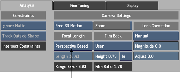
- While in Analyzer 3D view, drag each of the four corners of the rectangle to the desired location to form a rectangular grid. The rectangle automatically aligns to the new perspective. The Range Error, which displays the error estimate for the focal length, should be small relative to the focal length (should be less than 10% of the focal length). When dragging one of the corner points of the rectangle, if your desired location cannot be computed (for example, if a point goes past another point on the plane), the location is remembered with a dotted line and red circle. Once you move other corners, your original location may now become viable, and the rectangle and grid align properly. (See Perspective Grid for details on placing the corner points.)
- If you want to add manual trackers pre-process, do so now.
- Click the Analyze button to start the tracking.
- When the tracking analysis is complete, click Confirm.