There are 3 ways to create extruded features, from a sketch profile, a face, or from a primitive.
What's New: 2020, 2021.1, 2021.2, 2022
When you create extrusions from a sketch profile, the extruded result that you specify, solid or surface, determines the geometry that you can select. For example, when you specify a surface extrusion, you can select open or closed loops made up of sketch curves or projected face edges. When you specify a solid extrusion, you can select either loops or regions.
Creating sketch features from primitive shapes automates the sketching and extrusion process. In the Primitive panel, you can use Box to create a square or rectangular feature or body, for example, or Cylinder to create a cylindrical feature or body. You select a start plane for the sketch, define the profile, and then create an extruded solid.
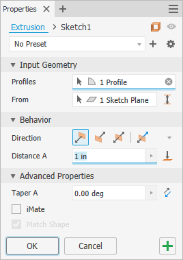
The Extrude command uses a property panel to define the feature. If you are not familiar with Inventor property panels, see About Property Panels to learn about the workflow, behaviors, and advanced options, such as the panel menu and advanced settings. Keep in mind the selections you make in a section, determine the options presented in the next section, as you work from top to bottom in the property panel.
Presets are hidden by default. If you want to create extrusion presets for commonly used shapes, in the Advanced Settings menu, uncheck Hide Presets. To learn more about presets see To Work with Presets.
Create an extrusion from a profile
- A new sketch, with one or more profiles, that have not been used to create any features.
- A sketch with geometry that creates one or more closed regions.
- An existing sketch that has been consumed by a feature and is visible when the command is initiated. The Advanced menu option Keep sketch visible on (+) is on by default.
- No sketch, no problem! The sketch command starts. Click on a workplane or face and begin sketching.
- On the ribbon, click
3D Model tab
 Create panel
Extrude
Create panel
Extrude
 .
.
If there is only one profile in the sketch, it is selected automatically. Otherwise, select a sketch profile.
- By default Extrude creates a solid body from an open or closed profile. You can also extrude a sketch as a surface body from an open or closed profile.
At the top of the property panel is the breadcrumb. To the right of the breadcrumb select Surface mode
 . The selection determines the options presented in the property panel. The Surface mode state (ON/OFF) is saved with presets.
Note: Surfaces function as a construction surface on which to terminate other features, or a split tool to create a split part, or split a part into multiple bodies. Surface selection is not available for assembly extrusions or primitives.
. The selection determines the options presented in the property panel. The Surface mode state (ON/OFF) is saved with presets.
Note: Surfaces function as a construction surface on which to terminate other features, or a split tool to create a split part, or split a part into multiple bodies. Surface selection is not available for assembly extrusions or primitives. - Specify the
Input Geometry. You can use window select to quickly select multiple closed profiles within the same sketch.
Note: Use the From and To options to get the same result as the Distance from Face and Between methods used in prior releases.Important: During feature preview visible sketch dimensions can be edited without entering the sketch environment.
- Profile(s) - the Profiles selector is active by default and when there are:
- One profile - if the sketch contains only one closed profile, it is automatically selected.
- Multiple profiles - select the profiles or regions that defines the desired extrusion or body.
Note: For part features, you can use a shared sketch as a profile.- In the browser, click the plus sign beside the feature that contains the sketch you want to use to expose th sketch node.
- Right-click the sketch icon and click Share Sketch. Any sketch that you use in more than one feature is automatically shared.
To manually share a sketch:
- From - As the default, the extrusion starts from the sketch plane. To change the selection, in the From field, click the 'x' to clear the selection and choose a different starting plane. Work planes, sketch planes, and planar faces are valid input.
 Between - use when extruding a shape between two faces. Select From and To faces, then select the Output type. The sketch doesn't have to be on either face.
Note: If the solution isn't what you were looking for with the Default direction, click Flipped direction and toggle Alternate Solution to see additional solutions.
Between - use when extruding a shape between two faces. Select From and To faces, then select the Output type. The sketch doesn't have to be on either face.
Note: If the solution isn't what you were looking for with the Default direction, click Flipped direction and toggle Alternate Solution to see additional solutions.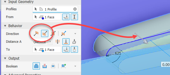
 Extend face to end feature - automatically activates when the
From selection does not intersect the extruded profile. You can also manually turn on or off the option. To turn the option off, click
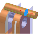
. The following is an example for how From and To are used together:
Extend face to end feature - automatically activates when the
From selection does not intersect the extruded profile. You can also manually turn on or off the option. To turn the option off, click
. The following is an example for how From and To are used together:
- Profile(s) - the Profiles selector is active by default and when there are:
- Specify the
Behavior parameters, first choosing from the available options:
 Direction: Default - Extrudes in one direction only. The extrusion end face is parallel to the sketch plane.
 Flipped Direction - Extrudes in the direction opposite of Direction.
 Symmetric - Extrudes in opposite directions from the sketch plane, using half the specified Distance A value in each direction.
 Asymmetric - Extrudes in opposite directions from the sketch plane using two values, Distance A and Distance B. Enter a value for each distance. Click
 to invert the extrude direction using the specified values.
- Distance A - specifies the depth of extrusion between start and end planes. For a base feature, shows negative or positive distance of extruded profile or entered value. Dragging the manipulator will modify the value.
- Distance B - specifies the depth in the secondary direction. Displays when Asymmetric is selected.
 Through All - extrudes the profile through all features and sketches in the specified direction. Dragging the edge of the profile flips the extrusion to either side of the sketch plane. The Join operation is not available.
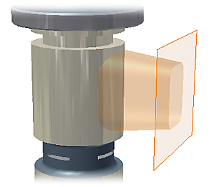
 To - For part extrusions, selects an ending point, vertex, face, or plane on which to terminate the extrusion. For points and vertices, terminates the part feature on a plane parallel to the sketch plane which passes through the selected point or vertex. For faces or planes, terminates the part feature on the selected face, or on a face that extends beyond the termination plane.
-
Extend face to end feature - automatically activates when the
From selection does not intersect the extruded profile. You can also manually turn on or off the option.
-
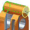
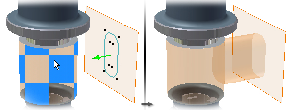
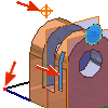
 Alternate Solution - when options for termination faces are ambiguous, specifies that the extrusion terminates on the closest face. With Alternate Solution selected, the extrusion terminates on the near side of the cylinder:
With Alternate Solution deselected, the extrusion terminates on the far side of the cylinder:
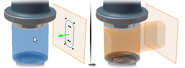
Alternate Solution is not applicable to and does not display in the property panel when planar faces are selected as the To face.
For assembly extrusions, you can select sketch points, vertices, faces, and planes that reside on other components. To be selected, work planes and work points must reside on the same assembly level as the assembly extrusion you are creating.
 To Next - (Not available for base features or assembly extrusions.) Selects the next possible face or plane on which to terminate the extrusion in the specified direction. Dragging the manipulator flips the extrusion to either side of sketch plane. Use the Terminator selector to select a solid or surface on which to terminate the extrusion and select a direction for the extrusion.
Note: To be valid, the next face or body must completely intersect the profile being extruded.
To Next - (Not available for base features or assembly extrusions.) Selects the next possible face or plane on which to terminate the extrusion in the specified direction. Dragging the manipulator flips the extrusion to either side of sketch plane. Use the Terminator selector to select a solid or surface on which to terminate the extrusion and select a direction for the extrusion.
Note: To be valid, the next face or body must completely intersect the profile being extruded.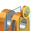
- In the
Output section specify the Boolean operation, choosing from:
 Join - Adds the volume created by the extruded feature to another feature or body. Not available for assembly extrusions.
 Cut - Removes the volume created by the extruded feature from another feature or body.
 Intersect - Creates a feature from the shared volume of the extruded feature and another feature. Deletes material that is not included in the shared volume. Not available for assembly extrusions.
 New Solid - Creates a solid body. If the extrusion is the first solid feature in a part file, this selection is the default. Select to create a separate body in a part file with existing solid bodies. Each body is an independent collection of features, separate from other bodies. A body can share features with other bodies. If desired, rename the body.
If there are multiple bodies in the part file, click the Solids selector in the Output section to choose one or more participating bodies.
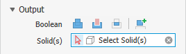 Note: In a multi-body part the feature preview will not display until a solid or New Solid is selected.
Note: The Output section displays for non-base feature definition. If the feature is the part base (first) feature, Join is the only create operation available.The command previews the Boolean operation direction. To turn off the predictive nature of the command, in the property panel advanced menu, click (to uncheck) Predict Boolean Operation. When checked the direction is predicted.
- In the Advanced Properties section you can specify additional options.
- Taper A - sets a taper angle from 0 to 180 degrees normal to the sketch plane. The taper extends equally in both directions.
Note: The in-canvas controls activate when the property panel edit field is clicked into.A positive taper angle increases section area along the extrusion vector:
 A negative taper angle decreases section area along the extrusion vector:
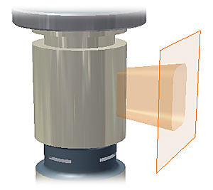 When used with adjacent regions, taper will merge and blend faces to create a single feature.
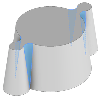
- iMate - Places an iMate on a closed loop such as an extruded cylinder, revolved feature, or hole. Autodesk Inventor attempts to place the iMate on the closed loop most likely to be useful. In most cases, place only one or two iMates per part.
- Match Shape - If you select an open profile in a part file, specify whether you want to Match Shape and, if so, select the side to keep.
If selected, Match Shape creates a flood-fill type operation. The open ends of the profile extend to a coedge, or face. The required faces quilt together to form a complete intersection with the extruded body.
When deselected, the open profile closes by extending the open ends of the profile to the part. It closes the gap between them by including edges defined by the intersection of the sketch plane and the part. Creates the extrusion as if you specified a closed profile.
- Taper A - sets a taper angle from 0 to 180 degrees normal to the sketch plane. The taper extends equally in both directions.
- Click OK or
 (Create new feature) to continue defining revolved features.
Create an extrusion terminating at a distance from a face
The profile sketch does not have to lie on the originating plane for the extrusion.
- Click
3D Model tab
Create panel
Extrude
.
- If there is only one profile in the sketch, it is selected automatically. Otherwise, select a sketch profile.
- Select the face, work plane, or surface from which to start the extrusion. The option
Extend face to end feature automatically activates when the
From selection does not intersect the extruded profile. You can manually change the option.
- Specify the
Behavior options, which could be direction and distance, to another face, and so on. Based on the selection the Terminate feature by extending the face option may be turned on. If the solution is ambiguous, such as when terminating to a curved surface, try applying the
Alternate Solution option.
Note: When working with a multi-body solid, you will need to specify the extrusion as part of another body by activating the Solid(s) selector and clicking the desired body or as a new body.
- Click OK or
(Create new feature) to continue defining revolved features.
Create an extrusion from a primitive
- Click
3D Model tab
Primitives panel
Box
 or
3D Model tab
Primitives panel
Cylinder
or
3D Model tab
Primitives panel
Cylinder
 .
.
- Select a sketch plane. The sketch plane can be an origin plane, a work plane, or a planar face.
- Define the shape by doing one of the following:
- For a box, click to define the center and then click to define a corner.
- For a cylinder, click to define the center and then click to define the diameter.
- Specify the
Behavior parameters, first choosing from the available options:
-
Direction (default) - Extrudes in one direction only. The extrusion end face is parallel to the sketch plane.
-
Flipped Direction - Extrudes in the direction opposite of Direction (default).
-
Symmetric - Extrudes in opposite directions from the sketch plane, using half the specified Distance A value in each direction.
-
Asymmetric - Extrudes in opposite directions from the sketch plane using two values, Distance A and Distance B. Enter a value for each distance. Click
to invert the extrude direction using the specified values.
- Distance A - specifies the depth of extrusion between start and end planes. For a base feature, shows negative or positive distance of extruded profile or entered value. Dragging the manipulator will modify the value.
- Distance B - specifies the depth in the secondary direction. Displays when Asymmetric is selected.
-
Through All - extrudes the profile through all features and sketches in the specified direction. Dragging the edge of the profile flips the extrusion to either side of the sketch plane. The Join operation is not available.
-
To - For part extrusions, selects an ending point, vertex, face, or plane on which to terminate the extrusion. For points and vertices, terminates the part feature on a plane parallel to the sketch plane which passes through the selected point or vertex. For faces or planes, terminates the part feature on the selected face, or on a face that extends beyond the termination plane. Click
Extend face to end feature to terminate the part feature on a face that extends beyond the termination plane.
For assembly extrusions, you can select sketch points, vertices, faces, and planes that reside on other components. To be selected, work planes and work points must reside on the same assembly level as the assembly extrusion you are creating.
-
To Next - (Not available for base features or assembly extrusions.) Selects the next possible face or plane on which to terminate the extrusion in the specified direction. Dragging the manipulator flips the extrusion to either side of sketch plane. Use the Terminator selector to select a solid or surface on which to terminate the extrusion and select a direction for the extrusion.
- In the
Output section, specify the Boolean operation, choosing from:
-
Join - Adds the volume created by the extruded feature to another feature or body. Not available for assembly extrusions.
-
Cut - Removes the volume created by the extruded feature from another feature or body.
-
Intersect - Creates a feature from the shared volume of the extruded feature and another feature. Deletes material that is not included in the shared volume. Not available for assembly extrusions.
-
New Solid - Creates a solid body. If the extrusion is the first solid feature in a part file, this selection is the default. Select to create a separate body in a part file with existing solid bodies. Each body is an independent collection of features, separate from other bodies. A body can share features with other bodies. If desired, rename the body.
If there are multiple bodies in the part file, click the Solids selector in the Output section to choose one or more participating bodies.
Note: In a multi-body part the feature preview will not display until a solid or New Solid is selected.The command previews the Boolean operation direction. To turn off the predictive nature of the command, in the property panel advanced menu, click Predict Boolean Operation. When checked, the direction is predicted.
- In the Advanced Properties section you can specify additional options.
- Taper A - sets a taper angle from 0 to 180 degrees normal to the sketch plane. The taper extends equally in both directions.
A positive taper angle increases section area along the extrusion vector:A negative taper angle decreases section area along the extrusion vector:
- iMate - Places an iMate on a closed loop such as an extruded cylinder, revolved feature, or hole. Autodesk Inventor attempts to place the iMate on the closed loop most likely to be useful. In most cases, place only one or two iMates per part.
- Match Shape - If you select an open profile in a part file, specify whether you want to Match Shape and, if so, select the side to keep.
If selected, Match Shape creates a flood-fill type operation. The open ends of the profile extend to a coedge, or face. The required faces quilt together to form a complete intersection with the extruded body.
When deselected, the open profile closes by extending the open ends of the profile to the part. It closes the gap between them by including edges defined by the intersection of the sketch plane and the part. Creates the extrusion as if you specified a closed profile.
- Taper A - sets a taper angle from 0 to 180 degrees normal to the sketch plane. The taper extends equally in both directions.
- Click OK or
(Create new feature) to continue defining revolved features.
Editing an Extruded Feature
- In the graphics window or the browser, right-click the feature and choose Edit Feature. You can double-click the browser node to edit the feature.
The property panel displays.
- Change defining values, the method to terminate the feature, or whether it joins, cuts, intersects another feature, or is a new feature.
To Edit the feature sketch, in the property panel breadcrumb text, click the Sketch# and begin editing the sketch. For more information see To Create and Edit Sketches.