Customize many aspects of Netfabb appearance and behavior
Jump to:
- About the settings
- User interface
- General
- Import and export
- Display settings
- Netfabb Application Service
- Slice Commander
- Support Module
- Orient Part
- Part Repair
- Generate Label
- 3S Executor
- 3S Generator
- Toolpath
- Part Renaming
- Short-Cuts
About the settings
The product settings are stored in two locations, the Windows® registry (HKEY_CURRENT_USER\Software\Autodesk\Netfabb) and in a database file (%userprofile%\AppData\Roaming\netfabb\ConfigDatabase).
To change
Netfabb's settings, open
 Settings > Settings. Some of the settings involve picking colors. For instructions on how to use the color selector, see
Change Colors.
Settings > Settings. Some of the settings involve picking colors. For instructions on how to use the color selector, see
Change Colors.
You can export your settings to an XML file using the buttons in the dialog here.
During import, you can choose which sections to import from the XML file.
TopUser interface
|
Language |
Current available languages are English, German, Japanese, Chinese simplified, Chinese traditional, Korean, French, Spanish, Portuguese (Brazilian). |
|
Font Size |
Provides five fixed font sizes as well as an option that lets Netfabb determine a font size appropriate to current screen resolution and DPI.
Note: Netfabb may determine an incorrect font size when on-screen text is scaled beyond 100 % by Windows® itself (Windows 10: "Make everything bigger"). This may cause text to be overly large, and window elements to be hidden behind the task bar, even on screen resolutions that meet the system requirements.
|
General
|
Start without license |
Enables Netfabb to launch straight into the license-free Netfabb Basic regardless whether a trial period or any subscription is active. When this is set to Yes, and a trial has expired, it also disables the licensing reminder. |
|
Unit of length |
Switches between millimeters and inches as default units |
|
Proxy settings |
Updates and the Online Help require an Internet connection. Using the options here, you may set them independently from your system's proxy settings. |
|
Netfabb logging |
Set path for storing log files, and logging priority level. By default, the path is, or is equivalent to, %userprofile\AppData\Roaming\netfabb\netfabb.log. If you encounter any errors and want or need to contact support, we strongly recommend adding this file to your support case. When you can reproduce the issue, it's a good idea to set logging to a lower level such as Info and repeat triggering the issue so that more logging information is generated before you add the log file to the case. |
|
Database type |
Sets type and, if non-local, connection to the database that stores certain information and configuration. For example, measurements and My Machines configurations are stored in a database. The local database is stored at %userprofile%\AppData\Roaming\netfabb\ConfigDatabase. |
|
Rotation with mouse, discretation degree |
When rotating objects manually, hold ALT to rotate the objects in steps of this angle. |
|
Rotation X, Y, Z degree |
When rotating by the X, Y or Z key, the part will rotate in steps of this angle. |
|
|
Rotating multiple selected parts at once normally rotates them all around a common axis as if they were shells of one single part. Whit this set to Yes, those parts are rotated individually around their own axis. |
|
Colors |
Set the colors for platform, parts, and modules. |
|
Default platform shape |
Toggle between a cubic or a cylindrical platform shape. |
|
Default platform size |
The size of the platform is best adjusted to the size of the build platform in your machine. |
|
Zoom to newly created parts |
When set to Yes, whenever you have created a part, the display will zoom into it. |
|
Automatic check for erroneous parts |
Check for faults in parts and display a warning sign if found. Check does not include self-intersections and degenerate triangles. |
|
Decimal separator for CSV export |
Period or comma |
|
Clip plane shortcut step |
|
|
Recent file count |
Set the number (1-20) of recently opened files to list in the File menu. |
|
Autosave |
Saves the currently open project in a selectable interval. Can be switched off. |
|
Reverse zoom direction |
Determines the direction of zooming for the mouse wheel. |
|
Default orbit type |
Orbiting the camera about the parts can be free (around the Z axis of the viewport) or constrained (around the Z axis of the build platform):  Free orbit (left) and constrained orbit (right) |
|
Warn if solid model associativity will get lost |
Mesh-based work such as cutting or repair on parametric models requires turning them into actual meshes. This option switches the warning message on or off that appears when launching such work on parametric models. |
|
A360 Auto-Signin |
Switch whether to use a present Autodesk Account login for logging into A360. |
 Rotate individually
Import and export
|
Resolve Windows link file names |
This setting determines the naming of parts that are opened with a link file (LNK) that links to a 3D file. If it is inactive, the part in the project is named as the LNK file, when it is active it is named as the 3D file. |
|
Ask for saving while deleting part |
When you want to remove a part, Netfabb will prompt you to confirm this. |
|
Change LOD for all opened files |
All parts and project will automatically be opened with this level of detail (LOD) value. |
|
Restore LOD after project loading |
Whenever working with a lower LOD in order to speed up processing, this switch saves it to continue working with this LOD next time. |
|
Confirm after project saving |
When this option is activated and you save a project, you’ll get a confirmation when the process has been finished. |
|
Always use file preview |
When you select Yes, the File Preview Browser will start every time you want to open a file. |
|
Ask for saving while opening a project |
When you have an unsaved project loaded, you are asked for confirmation when you attempt to open another project. |
|
3MF import |
Select whether to always split 3MF build items, and to always ask for splitting with this file type. You may also select whether to interpret 3MF components as Netfabb groups. |
|
ASCII-STL import |
Select whether to always split ASCII-STL solids, and to always ask for splitting with this file type. |
|
CAD import |
Contains options regarding assembly splitting. |
|
Use netProject cache |
Select whether to use this feature |
|
Use advanced file import |
When this is activated, a dialog box appears where you can change the settings for the import and stitch, scale, and duplicate parts. |
|
Use shorter texture names |
Select whether to shorten names of textures. |
|
Pentaho reporting SDK folder |
Specify the path for storing these files. |
|
Java executable |
Specify the directory location of Java, needed to generate reports using Pentaho templates. |
Display settings
|
Strength of background gradient |
Set a percentage value for the amount of color change in the gradient that goes from bright at the top of the display to dark at the bottom. The default color is white, which becomes grey at the bottom. |
|
Use enhanced display functions (OpenGL3.3) |
The enhanced display functions enables a more detailed rendering of parts, and accelerates certain operations as their data is retrieved directly from the graphics hardware rather than having to separately calculate it. If you have trouble with displaying your parts, set this switch to No. Note that this also disables and/or hides any transparency as well as related options and switches. |
|
|
Integrated graphics by Intel® may not support the display functions of OpenGL3.3 used by Netfabb well or at all, which is why they are disabled by default on these graphics units. You can bypass the check for Intel graphics here. |
|
Level of detail |
Use the Simple mode for faster calculation, or Advanced for a more precise view of the part. |
|
Highlight center of platform |
Two lines along X and Y mark the center point along them and, where they cross, the center of the platform itself. |
|
Animated Perspective Switch |
Toggles whether changing between default perspective should be animated or instantaneous. |
|
Use vertex buffer objects |
Specify whether to use vertex buffer objects, an OpenGL feature to increase performance when copies of parts are involved. Rather than rendering each part individually, only the original is kept in memory while the copies are drawn as instances of the original. |
|
Antialiasing |
Specify whether to use antialiasing for smoothed drawing of edges. This feature uses a lot of processing power, however, and might decrease performance. |
|
|
With this setting active, clicking the visibility icon in the project tree cycles through
This transparency stacks with any transparency or visibility commanded by the use of the clip planes. |
|
|
Set a percentage value for the strength of transparency used when parts are set to transparent. |
|
|
When an OBJ file carries normals information, switching this to Yes makes the Netfabb renderer use it for surface shading, producing a smoother appearance. Otherwise, even when normals information is present, Netfabb uses its regular flat shading of triangles. |
|
|
By default, the highlighting of cross sections is occluded wherever part surfaces are in front of them. Set this to Yes to always have them drawn in front of any part surfaces, occluding or not. |
|
Transparency of cuts |
Set a percentage value for the strength of transparency used with the clip planes and for cutting. |
|
Coordinate system |
The perspective indicator, a representation of the global coordinate system can be configured in several ways. Set here its size as a percentage of the display's size, as well as the visibility and size of the colored planes. They vary between the minimum and maximum value, depending on the current perspective, with planes in the background always displayed larger than those in the foreground. The planes, when displayed, can be used for changing the perspective by clicking on them. This is also where you switch between the regular perspective indicator and the viewcube, and in which corner of the display it sits. 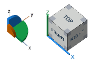 The two styles of perspective indicator in Netfabb: the coordinate system and the viewcube |
|
Ruler |
Change color and visibility (transparency) of the ruler displayed at the bottom of the display. |
 visible,
 transparent, and
 hidden instead of just switching between
Netfabb Application Service
|
Enable Server Access |
Allow a Netfabb Application Service server to use this Netfabb instance, when running, for performing queued tasks |
|
Server URL |
This is the URL where this instance of Netfabb can register itself with the NAS server behind it. |
|
Server passphrase |
The required access control passphrase, if set in the server. |
Slice Commander
|
Colors |
Define here the colors for a number of UI elements that are used when working in the
|
|
Release loaded slice files |
Slice files are usually loaded only partly to save on RAM requirements. However, this locks the files against access by other processes including Netfabb itself, when you load slice files generated by a machine, for example. To always load the entire slice file into memory and allow other processes access, set this to Yes. |
|
Highlighting Grid Size |
To highlight the interior of a closed contour, a placeholder hatching can be displayed. With this option, specify how tightly the lines for the placeholder filling should be spaced. |
|
Highlighting Style |
Select in which direction the lines should point (read: which axis they should be parallel to) that are used for the placeholder hatching, in X, Y, or X and Y. 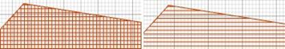 Highlighting examples: Along both axes (left) and along X axis only (right). |
|
|
|
|
Default point reduction tolerance |
This is the default threshold up to which a change in shape is allowed when a point reduction is to be performed. |
 Slices
Support Module
|
Colors |
Set the colors used for the platform, mesh, supports, anchors, and down-oriented edges |
|
Number of decimal digits |
Specify how many decimal places should be used to display values. |
|
Zoom animation duration |
Set a time in milliseconds (ms) |
|
Show cutplanes |
Visualizes the use of clip planes not just with lines but with a graded plane similar to the ones used in plane cutting |
|
Zoom orientation |
Specify a perspective view or keep existing orientation when zooming |
|
Mouse action for bar support |
Specify whether a single or a double click is required to place a bar support manually. |
|
Ask on deletion of all support |
Yes or No |
|
Laser diameter for volume calculation |
Set a diameter value. Used to give open hatchlines a volume to be able to calculate a volume estimation |
|
Apply as part attachment |
Setting this to No creates the support structures as separate parts on the platform instead of parametric attachments to the supported parts. Some older applications and formats need this as they do not recognize dedicated support structures. For example, attached support is dropped when exporting meshes to STL instead of the modern 3MF.
Note: You can always convert support structures regardless how you generated them using the
Manage Support command in the
Home toolbar, but keep in mind that attaching a mesh that was parametric previously does not restore the parameters how it was generated, so you cannot edit them in the support editor.
|
|
Respect part environment |
When set to No, support structures get generated on a part regardless of the presence of other parts. |
|
Use voxelgrid for walls |
Supports near walls can interfere with the same walls. When using the voxel grid approach, the wall detection is improved but the calculation cost increases. |
|
Voxelgrid size, Voxelgrid height |
The size of the voxels determines accuracy of wall detection and avoidance but incurs proportional computation costs. |
 Show Apply behavior dialog Show Apply behavior dialog
|
When applying support from the support editor, you are asked with a dialog whether to keep or terminate the support editor entry in the project tree. The dialog contains a checkbox to choose to always use this dialog. After unchecking the box, your last choice is remembered and the dialog no longer appears. With this option, you get the dialog to appear again. |
Orient Part
|
Colors |
Set colors used for the various elements |
|
Area selection angle |
When marking areas that must not be considered supportable, this specifies up to which angle adjacent triangles may be tilted away to still become marked as well. |
Part Repair
|
Colors |
Set colors used for outer and inner shells, boundary edges, self-intersections, duplicate triangles, edges, extrusions and other part features. |
|
Default stitch tolerance |
This value is used to pre-set the maximum distance between border edges that will still get stitched. |
|
Minimum edge length for good faces |
Determines which triangles are defined as degenerated in the repair module. All triangles with a height lower than this value can be displayed in orange and are deleted with the function Remove degenerate faces. Triangles with an edge shorter than the specified value are highlighted. |
|
Allow Undo |
Set whether to allow any Undo during repair, and if yes, whether there should be a limit to either 100000, 300000 or 800000 triangles involved. Increasing and removing the limit also increases the potential memory requirement. When a limit is set, undoing a change that (in sum with previous changes in repair) changed more triangles, Netfabb cancels the repair entirely, but not without prompting you for confirmation. |
Generate Label
|
Colors |
Set colors for parts, backfaces, and two label types. |
|
Default depth |
Label dimension |
|
Default height |
Label dimension |
|
Default build type |
Add to part or subtract from part, and whether it should be inverted |
|
Default font |
Leave at "default", or double-click to select a font from those installed on the system. |
3S Executor
Set the colors used by Selective Space Structures for surface structures, parts, selections, volume data, surfaces, and other items.
Top3S Generator
|
Colors |
Set colors used for nodes, bars, backside faces, hatches, previews and other elements. |
|
Default raster size |
Specify three dimensions. |
|
Default cell size |
Specify three dimensions. |
|
Default layer thickness |
Small numeric value |
|
Default face thickness |
Small numeric value |
|
Default edge overlap |
Small numeric value |
|
Render package preview |
Yes or No. |
|
Enable undo in generator |
Yes or No |
Toolpath
Set colors used for elements such as axis filter, core, DLL, downskin, filling, and hatches as they appear in powderbed-fusion-type machine workspaces.
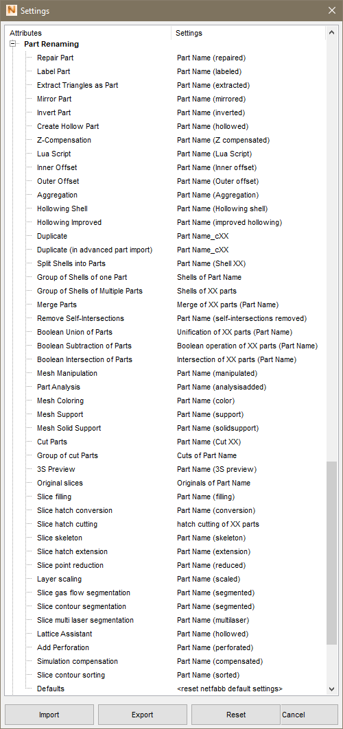
TopPart Renaming
The part renaming specifies the name applied to parts after they are modified, or more accurately, to the parts generated by those modifying actions. The name of the original is always part of the new name. To change renaming settings, double-click on a function in the list, or click on the button ..." which appears to the right of the function after you click on it once. A dialog appears to change the automatic renaming. You can insert what is added before or after the part name in the text fields left and right of part name. Below, you can see a preview of how your parts are named. "Part name" always refers to the name of the original part. With the button Set to defaults at the bottom of the dialog, you restore the default naming for that particular function. The default setting for repaired parts, for example, is that (repaired) is added to the original part name.
Create Hollow Part, Inner Offset, Outer Offset, and Hollowing Shell refer to the respective options for the function Create shell. Group of shells of one part and Group of shells of multiple parts stand for the names of the groups into which the shells are moved with Shells to parts. Similarly, Group of cut parts refers to the group into which cut parts are moved.
Functions for which the automatic part renaming can be altered
For functions that may create several parts at once, or that process several parts at once, such as Duplicate, Shells to parts, Cut parts, and Merge parts, there is the additional field XX. This is only enabled, when the box below is ticked. When several parts are created at once, the XX stands for a number which gets inserted for each part name. When you duplicate a part, for example, the copies are by default named Part name_c00, Part name_c01, Part name_c02, and so on. When several parts are processed by a function, the XX stands for the number of parts processed, as for example in Merge of 2 parts.
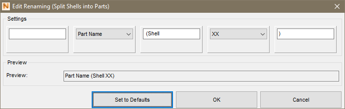
The dialog box for changing the automatic renaming for Shells to parts.
Any modified renaming items are written in italic letters. By using the very last item in the list, Defaults, you restore the default naming settings for all functions.
TopShort-Cuts
Keyboard shortcuts, such as Ctrl + S to Save Project, are listed here and can be modified. The shortcuts are arranged into categories:
- Global
- Default Module
- Part Export
- Part Repair
- Texture Module
- Support Module
- 3S
- Labeling
The shortcuts themselves are listed in a separate article.
Top