Contacts are used to define how parts in an assembly interact with one another. Examples include if the parts are bonded together and simply cannot move, if one part can slide relative to another, or if the two parts can separate from one another but cannot slide.
There are two primary ways to define contacts, Automatically and Manually.
Automatic Contacts
To run an Automatic contact calculation, click Automatic from the Contacts panel in the ribbon:

This causes Inventor Nastran to identify contact pairings throughout the model and assign a contact condition to each.
By default, all automatically-computed contact pairs are set to Bonded. This means that the two parts move together at the contacting surface due to forces acting on the model. To change the contact definition, right-click on the contact entry in the Tree, and click Edit. You can then select the desired contact type from the list:

Manual Contacts
Assigning contacts manually allows for greater control over the contacting surface pairs. To do this, click Manual from the Contacts panel in the ribbon:

On the Surface Contact dialog, there are two options for defining contacts:
Auto
The Auto option allows you to define multiple contacts automatically. You only need to define a single contact boundary for each contact pair.

Notes:
- The Tolerance and Max Activation Distance define the separation between two surfaces considered to possibly be in contact. The value is roughly the physical separation distance between the two entities.
- The Stiffness Factor is the stiffness of the contact joint. This value is based on the stiffer of the two joined sections. Use the default value if the two entities have similar stiffness values.
Manual
With the Manual option, you specify the primary and secondary surfaces or edges involved in the contact.
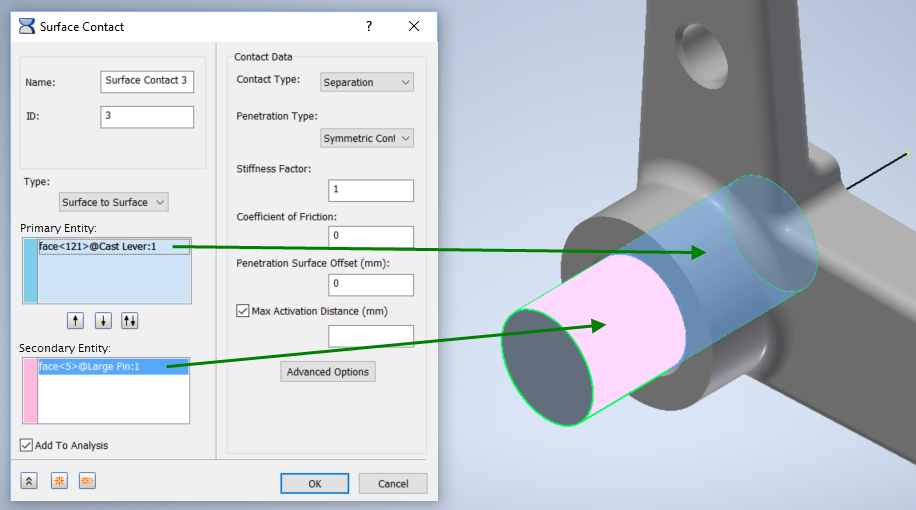
The primary surface usually has the more coarse mesh. The secondary surface cannot penetrate the primary. The use of a symmetric Penetration Type eliminates the distinction.
Notes:
- The Max Activation Distance should be slightly larger than the maximum expected sliding or motion.
- For similar surfaces, the default Stiffness Factor is acceptable. Reduce the value if one body is much softer than the other. Increase the value if the contacting entities penetrate one another too much.
Types of Contact
- Separation: This is a surface to surface contact, and allows sliding and opening between the entities at the contact location.
- Available in a nonlinear analysis.
- In a linear static analysis, it uses the linear contact solution. Only the areas which are making contact are being used. The areas trying to lift off are ignored.
- It will include friction effects.
- Bonded: This contact causes the two items to react in the same way at the contact location. At the contact location, the pair cannot separate, nor can the items move relative to one another.
- Available in linear and nonlinear analysis.
- Sliding/No Separation: In tension and compression, this will allow for sliding along the contact face, but the parts will not be allowed to separate.
- Available in linear and nonlinear solutions.
- Works best for planar surfaces since curved surfaces require a little bit of lifting to accomplish sliding relative to one another (due to faceting of the mesh).
- Separation/No Sliding: The entities can come apart in tension and compression, but cannot slide relative to one another.
- Available only in nonlinear analysis.
- It's essentially infinite friction.
- Offset Bonded: This is used to simulate welded connections with significant separation between contacting surfaces.
- Available in linear and nonlinear solutions.
- Works for edge to surface contact, typical of what you would see with shell models or midsurface models.
Basic Guidelines
- In general, when selecting the Manual option to setup contact, choose the primary as the contact segment that has the least amount of curvature, or if it is cylindrical contact choose the primary as the outside segment (and use unsymmetrical penetration).
- Generally, when setting up a nonlinear analysis, use 5 increments for contact with no sliding, 10 increments for contact with sliding, and 20 increments for contact with nonlinear materials.
- For nonlinear analyses, run your model in a static/modal analysis first, and make sure it runs fine, and that the results look good. Note that the contact elements will behave as bonded (weld) elements during a static/modal analysis. If the results are as expected, proceed to a nonlinear analysis.
The Surface Contacts topic in the User's Guide contains additional information about contact modeling.
|
Previous Topic: Refine the Mesh Exercise |
Next Topic: Add Contact and Symmetry Exercise |