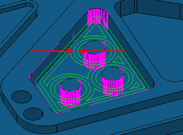
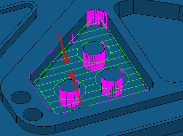
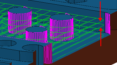
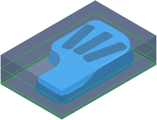
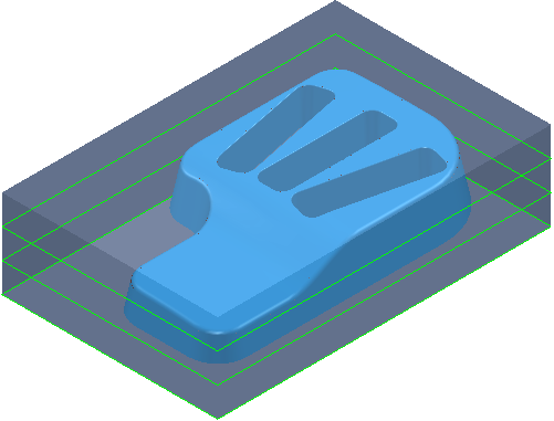
Use the Feature pocket profile page to create a toolpath by slicing the pocket features at specified Z heights and then creates a profile pass at each Z height. You can machine multiple pockets at different Z heights using one strategy. The Z heights are defined from the previous area clearance toolpath and are used to eliminate large terraces.
Cut direction — Select the milling technology.
Select a Cut Direction from the following:
-
Climb — Select to create toolpaths using only climb milling, where possible. The tool is on the left of the machined edge when viewed in the direction of tool travel.

-
Conventional — Select to create toolpaths using only conventional or upcut milling, where possible. The tool is on the right of the machined edge when viewed in the direction of tool travel.

- Any — Select to create toolpaths using both conventional and climb milling. This minimises the tool lifts and tool travel.
When you have several profile passes you can have a different cut direction for the final profile pass.
- Profile — Select the cut direction of the final profiling pass.
- Additional profiles — Select the cut direction of all passes except the final profiling pass.
Tolerance — Enter a value to determine how accurately the toolpath follows the contours of the model.
Thickness — Enter the amount of material to be left on the part. Click the
Thickness
 button to separate the
Thickness
box in to
Radial thickness
button to separate the
Thickness
box in to
Radial thickness
 Axial thickness
 . Use these to specify separate
Radial and
Axial thickness as independent values. Separate
Radial and
Axial thickness values are useful for orthogonal parts. You can use independent thickness on sloping walled parts, although it is more difficult to predict the results.
. Use these to specify separate
Radial and
Axial thickness as independent values. Separate
Radial and
Axial thickness values are useful for orthogonal parts. You can use independent thickness on sloping walled parts, although it is more difficult to predict the results.
Radial thickness — Enter the radial offset to the tool. When 2.5-axis or 3-axis machining, a positive value leaves material on vertical walls.

Axial thickness — Enter the offset to the tool, in the tool axis direction only. When 2.5-axis or 3-axis machining, a positive value leaves material on horizontal faces.

 Component thickness — Click to display the
Component thickness
dialog, which enables you to specify the thicknesses of the different surfaces.
Component thickness — Click to display the
Component thickness
dialog, which enables you to specify the thicknesses of the different surfaces.
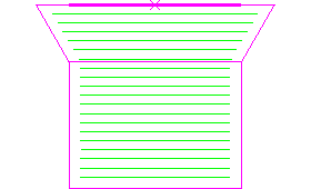
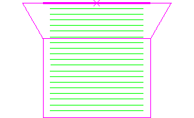
Stepover — Enter the distance between successive machining passes.
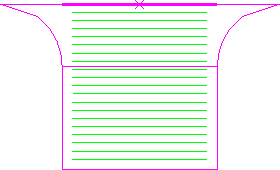
Stepover with a Style of Offset model:
Stepover with a Style of Raster:
 Copy stepover from tool — Click to load the radial depth of cut from the active
tool's cutting data. The radial depth of cut is measured normal to the tool axis.
Copy stepover from tool — Click to load the radial depth of cut from the active
tool's cutting data. The radial depth of cut is measured normal to the tool axis.
 .
.
Stepdown — Enter the distance between different machining levels.
-
Automatic — The
Stepdown value defines the Z heights, and deletes any existing Z heights.
Powermill creates a Z Height up to the Stepdown value entered, from the top of the block, and then steps down a defined height in Z. The final Z height is at the bottom of the block. The Stepdown definition takes into account existing Z Heights (such as those calculated when the Machine Flats option is selected). Powermill looks at pairs of existing Z Heights and adds the minimum number of extra Z Heights between them such that the stepdown between heights is less than or equal to the specified Stepdown value.
-
Manual — You specify the Z heights. Click the
Z Heights
 button to raise the
Area Clearance Z Heights dialog to specify the Z heights manually.
button to raise the
Area Clearance Z Heights dialog to specify the Z heights manually.
Copy stepdown from tool
— Click to load the axial depth of cut from the active
tool's cutting data. The axial depth of cut is measured along the tool axis.
.
Constant Stepdown — When selected, all the machining levels are equispaced, and the Stepdown value is a maximum stepdown. When deselected, the difference between consecutive machining levels is the Stepdown value for all levels except the last one which is at the bottom of the block.
Constant Stepdown deselected:
With a Stepdown of 20, the Z heights are at 15, -5, and -10.
The stepdown is the amount specified for all levels (in this case 20) except for the last one, which is at the bottom of the block (in this case a Stepdown of 5).
Constant Stepdown selected:
With a Stepdown of 20, the Z heights are at 20, 5, and-10. This gives an effective stepdown of 15.
The stepdown is the same between all levels but is not necessarily the amount specified. In this case, PowerMill uses a Stepdown of 15 rather than 20.
Rest machining — Select to change the strategy to Feature pocket rest area clearance and make the Rest page available with the options for rest machining. This option is not selected by default for this strategy.
Ignore chamfers — When selected the chamfers are not machined.
Ignore chamfers off.
Ignore chamfers on.
Ignore top fillets — When selected the top fillets are not machined.
Ignore top fillets off
Ignore top fillets on.