The information area of the Status bar enables you to create and activate workplanes, display various preset fields and display user defined fields.

 Workplane — Creates a new workplane of the selected type.
 Active Workplane — Select the active workplane. If no workplane is displayed, then the transform (global coordinate system) is used. Selecting one of the workplanes from the list makes it the active workplane.
 YZ Face — Use the YZ face of the workplane as the principal working plane. The active axes in the graphics window changes to
 .
.
 ZX Face — Use the ZX face of the workplane as the principal working plane. The active axes in the graphics window changes to
 .
.
 XY Face — Use the XY face of the workplane as the principal working plane. The active axes in the graphics window changes to
 .
.
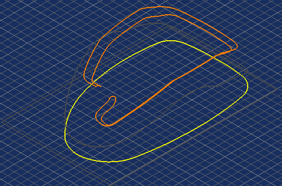
When the face is selected, any curves that you create are created in this plane. If it is not possible to create the curve in this plane, PowerMill creates the curve in a plane parallel to the principal editing plane.
 — Click to enable point-locking. When enabled, intelligent cursor snap points are projected onto the principal plane of the active workplane.
 Grid — Provides snapping points at regular intervals. The grid is placed on the principal plane (determined by which of
,
, and
is active).
Grid — Provides snapping points at regular intervals. The grid is placed on the principal plane (determined by which of
,
, and
is active).
The snapping points are at the intersection of the grid lines.
 Grid size — Distance between the grid lines.
 — The
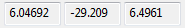
Coordinates of the cursor. These coordinates are determined by the intelligent cursor.
— The
Coordinates of the cursor. These coordinates are determined by the intelligent cursor.
 Position — Uses typed coordinate input rather than the cursor.
 Relative/Absolute Coordinates — Toggles between relative and absolute coordinates.
-
Relative Coordinates — The entities are moved by the amount specified in
 .
.
-
 Absolute Coordinates — The origin of the entities is moved to the coordinates specified in
.
Absolute Coordinates — The origin of the entities is moved to the coordinates specified in
.
Coordinates —Enter the coordinates here in the form x y z. For example, to move the origin by 10.4 in x, 25.6 in y, and 12.2 in z, enter
10.4 25.6 12.2.
 Calculation Queue— Displays a log of all entities added to the background calculation queue.
 — The current
Units (mm or inches).
— The current
Units (mm or inches).
 — The
Tolerance
of the active toolpath.
— The
Tolerance
of the active toolpath.
 — The
Thickness, or material to be left on, whilst the toolpath calculation is taking place. This can display either a general thickness parameter, or, if used, the radial and axial thickness values
— The
Thickness, or material to be left on, whilst the toolpath calculation is taking place. This can display either a general thickness parameter, or, if used, the radial and axial thickness values
 .
.
 — The diameter of the active tool.
 — The tip radius of the active tool.
Any User Defined Fields are listed at the end of the toolbar.