Tool axis limits controls angular limitations of the machine tool which therefore limits the angle at which a tool can be positioned while cutting a multi-axis toolpath.
This page contains the following:
Mode — Defines what happens to the toolpath when one of the angular limits is met. The effects of both of these options can be seen in Limiting a toolpath using tool axis limits.
- Remove toolpath — Select to remove the toolpath outside the angular limit.
- Move tool axis — Select to keep the tool axis at the machine limit on reaching an angular limit.
Use machine tool when possible — Deselect this option to manually calculate the tool axis limits. This option is selected by default.
Orientation — Select an option from the list to define the reference frame for the tool axis:
- Rotary axis configuration — Limits the tool axes relative to the machine tool rotary axes.
- Manual — Limits the tool axes relative to a selected workplane.
Workplane —Defines the workplane in which the angular limits are measured. By default, the active workplane is used. If no workplane is specified, then the global coordinate system is used. The effects of both of these options can be seen in Using a Clamping Workplane to specify toolpath limits. This option is available only if you have an Orientation of Manual.
Angle Limits —Defines the angular limits of the machine tool.
Azimuth Angle —Defines the angular limits of the machine tool in the XY plane. 0 is along the X axis; 90 is along the Y axis.
Elevation Angle — Defines the angular limits of the machine tool above the XY plane. 0 is in the XY Plane; 90 is along the Z axis.
A-axis limit — Select this option to apply limits to the machine tool's first rotational axis. Enter Min and Max values to define the limits.
B-axis limit — Select this option to apply limits to the machine tool's second rotational axis. Enter Min and Max values to define the limits.
The A-axis limit and B-axis limit fields are named after the rotary axis address of the machine tool. For example, if your machine tool has A and C rotary axes, the dialog displays A-axis limit and C-axis limit. The rotational axes must be orthogonal. These options are only available if you have an Orientation of Rotary axis configuration.
Damping Angle — The angle away from the limits at which damping (slowing down) will start to occur. If the axis is further away from the limits than this angle, then it will remain unaltered. If it is closer, then it will gradually be pushed away from the limits. In this way, if the axis is moving fast towards the limits, then it will slow down gradually, starting when it gets to within this angle from the limits. The advantages of using the damping angle is that a sudden change in the axis velocity can cause marks to appear on the part. Using a damping angle stops these marks.
Project to Plane — This is the same as setting the elevation angle to zero. Because the elevation angle is fixed, this usually produces a 4-axis toolpath. If the Z axis of the workplane used for rotary axis configuration is not aligned with a rotary axis of the machine tool, a 5-axis toolpath may be produced.
Draw Limits — Select this option to display a graphic of the machinable portion.
For example:
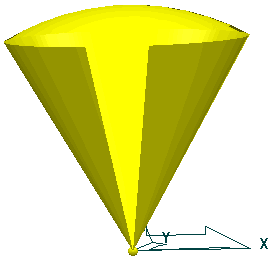
The portion of the sphere (or cone with a spherical top) is centred at the origin of the active workplane. If no active workplane exists, then it is placed at the origin of the global coordinate system. The origin is depicted by a small sphere. This graphic is displayed at an arbitrary size, and if you zoom in or out and then refresh the display, the size of this graphic changes. This is to ensure that it is visible whatever the zoom factor.
Translucency Percentage —If Draw Limits is selected, you can enter in this field the percentage translucency of the tool axis limits drawn on screen.
For more information see Limiting a toolpath using tool axis limits, Using a Clamping Workplane to specify toolpath limits, or Defining Limits for a Multi-Axis Machine.