Use the Model rest area clearance page to create a toolpath by slicing the model at specified Z heights and then creates an offset or raster pass at each Z height. The Z heights are defined from the previous area clearance toolpath and are used to eliminate large terraces.
Style — Select a toolpath style to use for removing material.
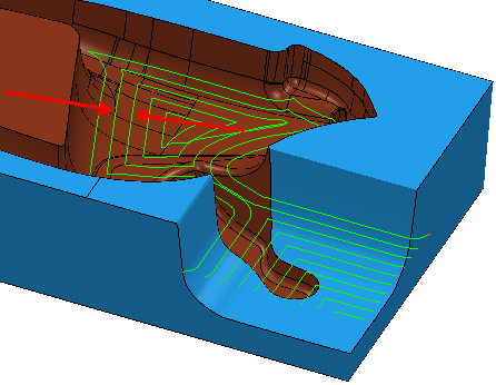
- Raster — This comprises of parallel straight-line moves in the X - Y plane.
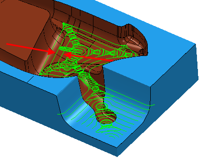
- Offset model — This clears an area with contours generated by repeatedly offsetting the initial slice until no further offset is possible. This produces a toolpath which maintains constant cut direction, tool load, and chip production. Additionally an Offset model toolpath avoids machining small or thin-walled upstands and minimises full width cuts.This option increases the number of tool lifts.
- Offset all — This produces an offset toolpath which minimises the number of tool lifts and works extremely well for soft materials.
- Vortex — This produces an offset toolpath which never exceeds the maximum tool engagement angle for optimum machining. As the tool approaches the maximum engagement angle, the toolpath changes to a trochoidal path to avoid tool overload. Vortex toolpaths are 3-axis toolpaths, so have a vertical tool axis.
Cut direction — Select a milling style for Profile and Area.
-
Climb — Select to create toolpaths using only climb milling, where possible. The tool is on the left of the machined edge when viewed in the direction of tool travel.

-
Conventional — Select to create toolpaths using only conventional or upcut milling, where possible. The tool is on the right of the machined edge when viewed in the direction of tool travel.

- Any — Select to create toolpaths using both conventional and climb milling. This minimises the tool lifts and tool travel.
Tolerance — Enter a value to determine how accurately the toolpath follows the contours of the model.
Thickness — Enter the amount of material to be left on the stock within tolerance.

 Component thickness — Click to display the
Component thickness
dialog, which enables you to specify the thicknesses of the different surfaces.
Component thickness — Click to display the
Component thickness
dialog, which enables you to specify the thicknesses of the different surfaces.
Stepover — Enter the distance between successive machining passes.
Stepover with a Style of Offset model:
Stepover with a Style of Raster:

Stepover with a Style of Vortex:
 Copy stepover from tool — Click to load the radial depth of cut from the active
tool's cutting data. The radial depth of cut is measured normal to the tool axis.
Copy stepover from tool — Click to load the radial depth of cut from the active
tool's cutting data. The radial depth of cut is measured normal to the tool axis.
 .
.
Stepdown — Enter the distance between different machining levels.

- Automatic — The Stepdown value defines the Z heights, and deletes any existing Z heights.
-
Manual — You specify the Z heights. Click the
Z Heights
 button to raise the
Area Clearance Z Heights
dialog to specify the Z heights manually.
button to raise the
Area Clearance Z Heights
dialog to specify the Z heights manually.
Copy stepdown from tool
— Click to load the axial depth of cut from the active
tool's cutting data. The axial depth of cut is measured along the tool axis.
.
Constant Stepdown — When selected, all the machining levels are equispaced, and the Stepdown value is a maximum stepdown. When deselected, the difference between consecutive machining levels is the Stepdown value for all levels except the last one which is at the bottom of the block.
Constant Stepdown deselected:
With a Stepdown of 20, the Z heights are at 15, -5, and -10.
The stepdown is the amount specified for all levels (in this case 20) except for the last one, which is at the bottom of the block (in this case a Stepdown of 5).
Constant Stepdown selected:
With a Stepdown of 20, the Z heights are at 20, 5, and-10. This gives an effective stepdown of 15.
The stepdown is the same between all levels but is not necessarily the amount specified. In this case, PowerMill uses a Stepdown of 15 rather than 20.
Rest machining — Select to make the Rest page available with the options for rest machining. This changes the strategy to a Model
This option is selected by default for this strategy. If deselected, the strategy changes to a Model Area Clearance strategy.