Use the Drilling page to control which holes to drill and how to drill them.
Cycle type — Select how to drill holes. Selecting an option displays the relevant Drilling page.
- Hole top — Drilling starts at the top of the hole.
- Component top — Drilling starts at the top of the component specified in the Top component field rather than the top of the hole. This is useful when drilling compound holes.
- Block — Drilling starts at the top of the block.
- Model — Drilling starts at the top of the model.
- Stock model — Drilling starts at the top of the stock. This displays the Stock page in the Drilling strategy dialog.
- Drill to hole depth — Drills to the hole depth. The Depth value is unavailable; it is specified from the Feature definition.
-
Full diameter —
PowerMill drills down until the widest part of the drill reaches the bottom of the widest part of the hole.
The drill tip may drill down further than the hole designed in the CAD model
 , or the drill tip may not reach the bottom of the hole
 .
.
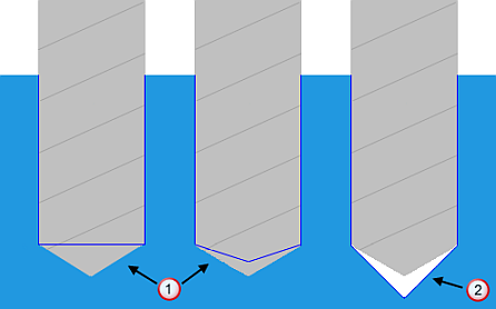
- Through hole — Drills through the hole. The Depth value is the hole depth, plus the height of the tapered part of the drill, plus a small factor.
- Centre drill — Centre drills the part. By default, the Depth value is the radius of the drill.
- Pre drill — Pre-drills to the hole depth. By default, the Depth value is defined from the Feature definition of the hole depth.
- Counter bore — Counter bores the part. By default, the Depth value is the radius of the drill.
- Chamfer — Chamfers the hole to the width specified on the Chamfer page.
- User defined — Drills all holes to a user-defined depth.
Define top by — Select the start places for drilling.
Operation — Select the drilling operation and drilling depth.
Components — Use to select both top and bottom components.
Top component — Select the start component for drilling. Drilling starts at the top of this component.
Bottom component — Select the last component for drilling. Drilling ends at the bottom of this component.
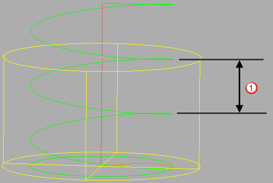
For example, a compound hole:
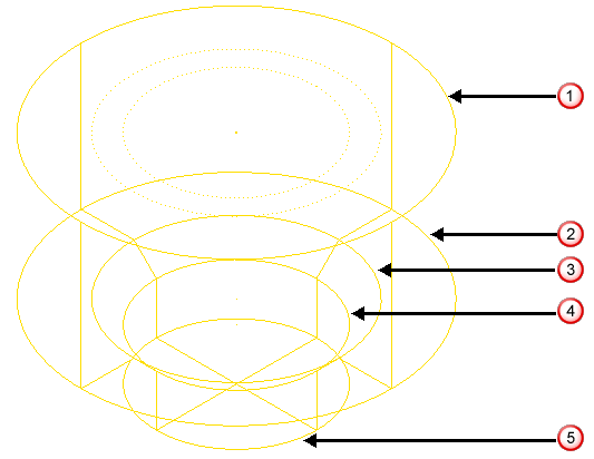
Looking at a side view:
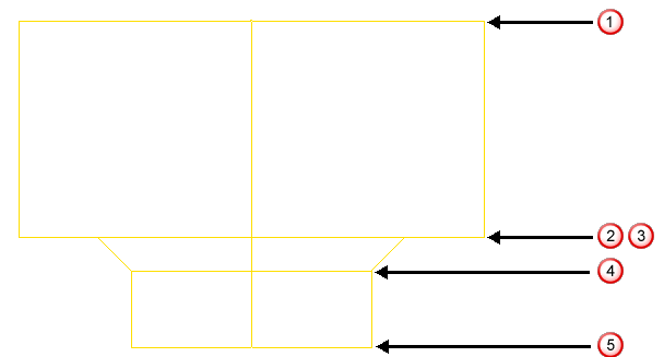
Hole top, first component top
First component bottom.
 Second component top.
 Second component bottom, third component top.
 Third component bottom, last component bottom.
and
are at the same Z height.
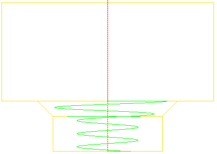
This example uses a Cycle type of Helical.
Top component of 2.
Bottom component of 3 or Last.
Clearance — Enter the distance above the top of the hole.
Peck depth — Enter the maximum distance the drill plunges in any one move.
Turns — Enter the number of turns of the thread milling tool. This defaults to 1. Long holes may need more than one turn. This option is only available for Thread milling strategies.
Pitch is either:
- The pitch of the helix for strategies such as Helical
- The thread pitch for strategies such as Tapping and Thread milling.
Tolerance — Enter a tolerance value to determine how accurately the toolpath follows the hole.
Start — Enter the incremental distance above the hole where you want the pecking to start. If you want to drill just to the top of the hole, enter a depth of 0 (depth is measured from the top of the hole). This is useful when you have a large amount of material above the top of the hole that must be removed using a drilling cycle.
Depth — Enter the depth of the drilling in the hole.
Dwell time — Enter the time the tool dwells before retracting at the end of each peck. This valuespecifies the length of time that the drill remains at the bottom of each peck.
Left hand — When selected, creates a left-hand thread. When deselected creates a right-hand thread.
Spiral — When selected, creates a spiral toolpath. The toolpath moves from the centre of each hole with a "tear drop" lead and spirals out using the Stepover defined on the Profile page.
Profile drilling toolpath with Spiral deselected:
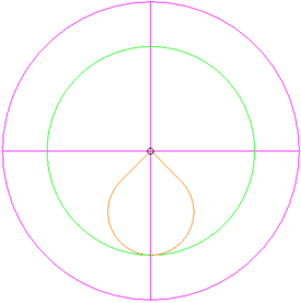
Profile drilling toolpath with Spiral selected:

Clockwise — When selected, creates a clockwise cycle. When deselected creates an counter-clockwise cycle.
Direction — Select the milling technology. The combination of Direction and Thread (on the Threading page) determines the cut direction.
|
Right hand thread |
Left hand thread |
|
|
Climb |
Clockwise, downwards |
Clockwise, upwards |
|
Conventional |
Counter-clockwise, upwards |
Counter-clockwise, downwards |
Thickness — Enter the amount of material to be left on the part, within tolerance.
 Radial thickness — Enter the radial offset to the tool. When 2.5-axis or 3-axis machining, a positive value leaves material on vertical walls.
 Axial thickness — Enter the offset to the tool, in the tool axis direction only. When 2.5-axis or 3-axis machining, a positive value leaves material on horizontal faces. A negative value enables you to drill a hole deeper than the hole feature. This is useful for through holes.
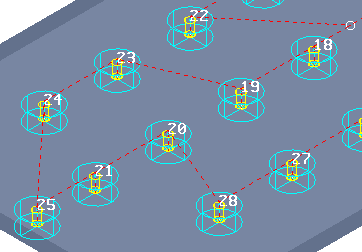
Draw — Select to display the tool in the selected holes and displays the hole names.
Drilling cycle output — Select to save as canned cycles. This should be selected only if your machine has cycles for helical and profile.
Select — Click to display the Feature Selection dialog which enables you to select holes by their diameter or length of a particular hole component. This selects the compound hole and not just the hole component.
 indicates a multi-axis drilling toolpath. This is displayed in the top right-hand corner of the dialog.
PowerMill knows when a drilling toolpath is multi-axis and defines the appropriate toolpath. Multi-axis drilling toolpaths are created when the holes have a different axis from the active workplane; 3-axis toolpaths are created when the holes have the same axes direction as the active toolpath.
indicates a multi-axis drilling toolpath. This is displayed in the top right-hand corner of the dialog.
PowerMill knows when a drilling toolpath is multi-axis and defines the appropriate toolpath. Multi-axis drilling toolpaths are created when the holes have a different axis from the active workplane; 3-axis toolpaths are created when the holes have the same axes direction as the active toolpath.