Use this dialog to define the geometric tolerances enclosed in the balloon.
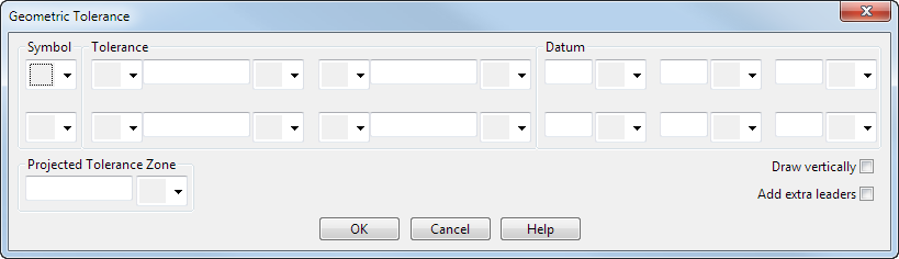
Symbol — Select a tolerance symbol from the list:
|
|
|
 Straightness
 Flatness
 Roundness
 Cylindricity
 Line profile
 Surface profile
 Parallelism
 Squareness
 Angularity
 Position
 Concentricity
 Symmetry
 Circular run-out
 Total run-out
Tolerance
- Select whether you want a diameter symbol:
 No diameter symbol
 Diameter symbol
- Enter the tolerance value.
- Select a material condition symbol:
None
 At maximum
 At least
 Regardless of feature size
Datum — This defines the datum from which the tolerances are measured.
To have two rows of geometric tolerance in the balloon, set the second row of Symbol, Tolerance, and Datum options.
Projected Tolerance Zone
- Enter a value.
- Select whether you want a projected tolerance zone symbol:
No symbol
 Projected tolerance zone symbol
Draw vertically — Select this option to create the balloon vertically, for example:

Add extra leaders — Select this option to have more than one leader, for example:

The Add Leaders dialog is displayed when you click the OK button.
OK — Creates the geometric tolerance balloon and closes the dialog.