Find the string to add to the template in one of the following ways:
- Identify the string to be added using the lists in Additional schedule parameters for use in Component Drawings.
- Record a macro as described below.
To record a macro that adds a column displaying the Thread Top Diameter of holes:
- Select a model.
- Click Draft tab > Drawing panel > New to display a new drawing in the graphics window.
- Create an object on the drawing and make it active.
- Click Home tab > Macro panel > Record. The Select a file to record to dialog is displayed.
- Enter an appropriate filename for your macro.
- Click Annotation tab > Table panel > Hole to display the Hole schedule dialog:
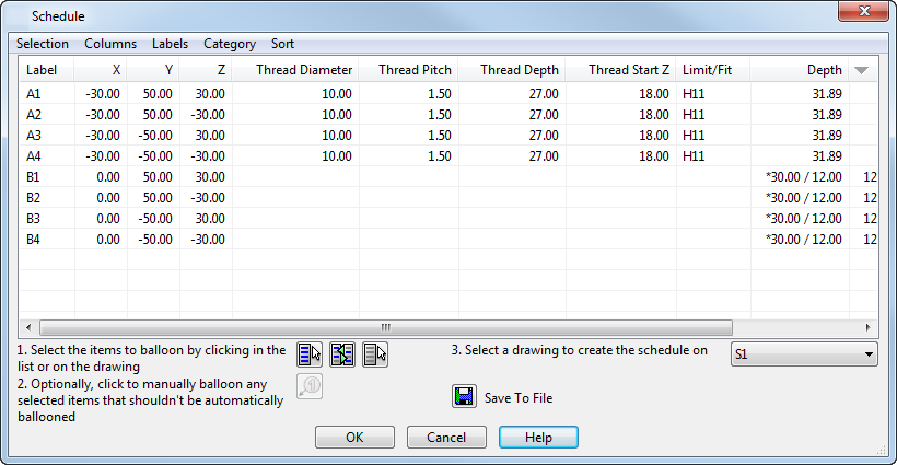
- Select Columns > Thread Details > Thread Top Diameter to select the option.
- Click OK.
- Click Home tab > Macro panel > Record to stop recording the macro.
- Open the macro file with a text editor. The commands look like this:
Create Schedule Schedule
SCHEDCOLUMNS ON THREADTOPDIAMETER
CANCEL
The item that you are interested in is THREADTOPDIAMETER
This must be added to the Component Drawing template.
- Open component_drawing_template.psmodel as described in Customizing the Component Drawings.
- Using the method described in Defining the BOM parameters on the GA sheet, open the required drawing templates. Schedules appear in the drawing templates:
component_sheet_plate_X - plate components.
component_sheet_userdefined_X - user-defined components.
- For each drawing template that is to display the additional column, double-click the Schedule list and add the following into the list:
COLUMN THREADTOPDIAMETER
The next time you create component drawings, the new columns are displayed.