You can add material onto a solid using wireframe objects. Behind the scenes, PowerShape creates extruded solids from the wireframe objects and adds them onto the active solid.

To create a solid boss:
- Select the solid and wireframe using one of the following methods:
- Make sure you have an active solid and then select the wireframe objects.
- Drag your cursor to select an inactive solid and the wireframe objects together.
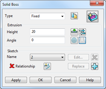
Note: The wireframe objects must be closed and planar. - Click Solid tab > Feature panel > Boss to display the
Solid Boss dialog:
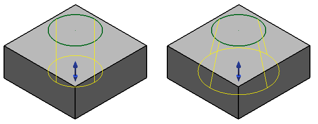
Each wireframe object is extruded to create the extruded solids. The direction of extrusion is defined by the position of the composite curve.
The extruded solid has a handle, which edits the length of all the extruded solids.

- Select the
Type of boss from the drop-down list:
- Select Automatic to extrude the wireframe just far enough to join to the solid. Specify the angle of the extrusion using the Angle option.
- Select Fixed to specify the Height of the extrusion. The extruded wireframe is added to the solid. The Extrude both directions option also becomes active.
- Click
 to create a copy of the original wireframe used in the construction of the boss.
- In the
Height box enter the length of each extruded solid, measured from the plane of the wireframe.

If you drag the handle of an extruded solid, the lengths of all the extruded solids change. The value of Height in the dialog updates to reflect the change.
To create bosses all the way through the solid, make sure the height extends beyond the base of the solid.
Enter the Angle to define a draft angle on the extruded solids.
To reverse the direction, drag the handle on the extruded solids to the opposite side of the wireframe.
- Click
 to extend the extrusion in both directions from the sketch. The button changes to
 to show that the extrusion is extended in both directions.
- Click
 to reverse the direction of the boss.
- Click
 to display the
Solid Feature Relationship dialog. This allows the position of the feature to be specified relative to the solid. The status of the
Relationship
is indicated by one of the following:
to display the
Solid Feature Relationship dialog. This allows the position of the feature to be specified relative to the solid. The status of the
Relationship
is indicated by one of the following:
 no relationship is currently defined.
 a valid relationship is defined.
 relationship is defined, but there is a problem with the definition
- Click
 to add the selected sketch (arc, curve or composite curve) to the feature.
- Click
 to
group nested sketches. This option nests any sketches that lie on the same plane and uses them to produce an island-type extrusion.
to
group nested sketches. This option nests any sketches that lie on the same plane and uses them to produce an island-type extrusion.
- Using two concentric circular sketches would produce a tube with a thickness.
- Using three concentric circular sketches, the tube would have a cylinder inside it.
- Click
 or
or
 to specify if the draft angle is to go in or out.
- Click
Apply
to create the boss, leaving the dialog displayed. This lets you:
- create another boss.
- edit the existing boss.
Alternatively, click OK to create the boss and close the dialog.
A Boss feature icon
 representing the operation appears in the solid feature tree.