Open the Cylinder dialog, which lets you define cylinders in Robot, using either method:
- Click Geometry menu > Objects > Cylinder.
- Click
 .
.
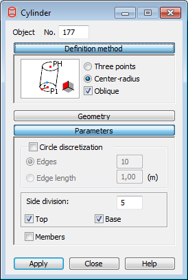
The dialog has four parts:
- Object field, which is the number of the created or selected object
- Definition Method
- Geometry
- Parameters.
When the Cylinder dialog is fully opened, clicking one of the 3 buttons (Definition Method, Geometry or Parameters) minimizes the corresponding part of the dialog so it displays only the options used at a given time. When the window is minimized, clicking one of the button extends the dialog.
Definition Method
Options for selecting the method for defining a cylinder are located in Definition Method. All available methods are based on defining 3 points which define the cylinder.
Defining a cylinder consists of 2 parts:
- Definition of the circle - the base of the cylinder
The diagrams show in general the methods for defining a circle as the base of a cylinder.

The circle is defined using 3 points on the circle. In the Geometry dialog, 3 fields: Point 1, Point 2, Point 3 are used.

The circle is defined by the center of the circle and by a point on the circle. In the Geometry dialog, Geometry Point P (the center of the circle) and Radius fields are used.
- Selecting the type of cylinder

The right cylinder
In the Geometry dialog, the Height (Cylinder Height) field is used.

The oblique cylinder
In the Geometry dialog, the Point PH (the point describing the position of the cylinder apex) is used.
Geometry
The fields in the Geometry dialog let you specify the coordinates for the suitable points of the cylinder. The number of points depend on the method you select for creating the base of the cylinder and the type of cylinder. In addition, there are buttons for choosing the plane for the base of the cylinder. To select the XY or XZ or YZ plane in which to position the base of the cylinder, click XY or XZ or YZ, respectively. The buttons are only available when the circle (base) is defined as by a center and radius.
- Specify the coordinates of the center of the circle as the base of a cylinder, the coordinates of the point on the circle and the height of the cylinder (graphically or entering values in the appropriate fields).
- Specify the coordinates of the center of the circle as the base of a cylinder, (graphically or entering the coordinates of the point ) and entering the values of a radius in the Radius field, the coordinates of the point on the circle, and the height of the cylinder in the Height field.
Parameters
The Discretization field is in the Parameters dialog.
When Circle discretization is cleared, the circle for the base of the cylinder is created using the analytical method.
When Circle discretization option is selected, you can define parameters for dividing the circle, which is the base of the cylinder:
- Edges - The number of sides of a polygon that approximates a circle (the polygon inscribed in a circle).
- Edge length - The length of the sides of a polygon that approximates a circle (the polygon inscribed in a circle).
It also has the following options:
- Top - If selected when defining the cylinder, the object wall (the top) is created.
- Base - If selected when defining a cylinder, the object wall (the base) is created.
- Solid - Selecting this option creates a cylinder as a volumetric structure (solid). The option is available for volumetric structures.
- Side division - Specifies the number of divisions along the height of the cylinder.
- Members - When selected this option, the cylinder consists of member elements (individual parts of a cylinder will be members). When the option is cleared, a cylinder is generated as a 2D object (plate, shell) or a 3D object (solid).
To define a cylinder:
- Select a method for defining the circle (the base of the cylinder).
- Define the type of the cylinder (right, oblique).
- Define the coordinates of the characteristic points on the circle as the base of the cylinder and the points defining the geometry of the cylinder:
- Specifying the coordinates of individual points in the Geometry dialog and clicking Apply.
- Graphically by clicking in the P1 in the dialog, then switching to the graphic layout and clicking on the point representing the first point on the circle, then clicking on the consecutive points.
- Combining both methods.
- Define the circle discretization parameters for the base of the cylinder (number of divisions in the suitable directions) and decide if the cylinder has a top or a base.