Sketch a line load along sloped or perpendicular structural elements.
- Select Structure tab
 Work Plane panel
 (Reference Plane).
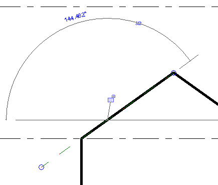
 - Draw a reference plane as shown.
- Click Structure tabWork Plane panel
 (Set).
 - In the Work Plane dialog, select Pick a Plane.
- In the drawing area, select the reference plane. The work plane is now set to the angle of the frame slope.
- Click Analyze tabAnalytical Model panel
 (Loads).
 - Click Modify | Place Loads tabLoads panel
 (Line Load).
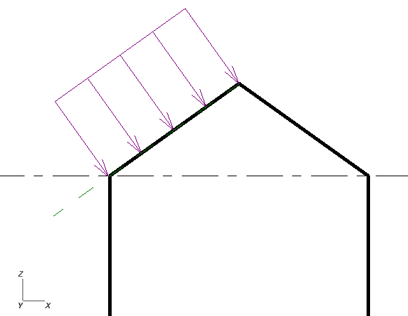
 - On the Properties palette, select a value for Load Case.
- For the Orient to parameter, select Work Plane.
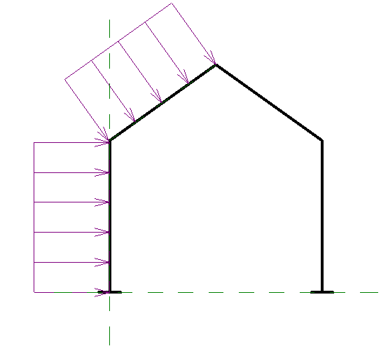
- Draw the line load as follows:
- Select the endpoint of the member that is at the base of the slope.
- Select the endpoint of the member that is at the top of the slope.
- Click Structure tabWork Plane panel (Set).
- In the Work Plane dialog, click Pick a Plane.
- Select the new reference plane.
- Click Analyze tabAnalytical Model panel (Loads).
- Click Modify | Place Loads tabLoads panel
 (Hosted Line Load).
 - On the Properties palette, enter a value for Load Case.
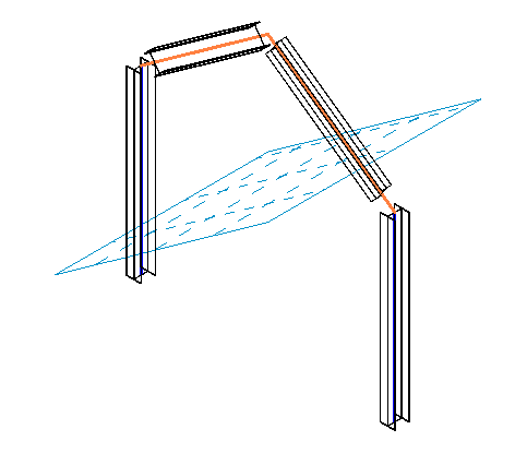
- Select a value for Orient to Host Local Coordinate System.
- Select the vertical member.
The Line load is added, perpendicular to vertical member in the positive x direction and created by using the work plane of the host.