The analytical projection plane references the location of, or the limits of, the structural member analytical model.
The following table defines the default plane for each structural element type.
| Structural Element |
Default Analytical Projection Plane |
|---|
| Columns |
Columns have an analytical projection plane at the top and the base of the column. These horizontal planes are offset from a level and define the limits of the structural column analytical model. |
| Structural Walls |
The central plane of the wall. |
| Beams |
Beams have an analytical projection plane parallel to the x-axis of the beam. The plane is defined at a plan level or relative to the beam section geometry. |
| Braces |
Relative to the brace section geometry. The plane is parallel to the x-axis of the brace. |
| Structural Floors |
The analytical projection plane of a structural floor is parallel to the plan level on first placement. Subsequent structural floor placements reference the last used projection plane. |
| Foundation Slabs |
The top face of the foundation slab. |
Each structural member analytical physical model has optional locations for its analytical projection plane. These projection plane locations are relative either to the levels of the structure or to the structural element itself. Change the location by adjusting the Vertical Parameter on the Analytical Model section of the Properties palette. The following are the possible projection locations for each structural element family:
Beams
| Start and End Projections |
|---|
| Horizontal reference (Y) |
Vertical reference (Z) |
|---|
| Location Line |
Location Line |
| Left of Element |
Top of Element |
| Center of Element |
Center of Element |
| Right of Element |
Bottom of Element |
| <Grids...> |
<Level...> |
| <Reference Planes...> |
<Reference Level...> |
| |
<Reference Planes...> |
Braces
| Start and End Projections |
|---|
| Horizontal reference (Y) |
Vertical reference (Z) |
|---|
| Location Line |
Location Line |
| Left of Element |
Top of Element |
| Center of Element |
Center of Element |
| Right of Element |
Bottom of Element |
| <Grids...> |
<Level...> |
| <Reference Planes...> |
<Reference Planes...> |
Columns
| Start and End Projections |
|---|
| Horizontal reference (Y) |
Vertical reference (Z) |
|---|
| Location Line |
Location Line |
| Left of Element |
Top of Element |
| Center of Element |
Center of Element |
| Right of Element |
Bottom of Element |
| <Grids...> |
<Level...> |
| <Reference Planes...> |
<Reference Planes...> |
| Vertical Extensions (X) |
|---|
| Top |
Base |
|---|
| Top Level Reference |
Base Level Reference |
| Top of Column |
Bottom of Column |
| <Level...> |
<Level...> |
| <Reference Planes...> |
<Reference Planes...> |
Structural Floors and Foundation Slabs
| Projection |
|---|
| Horizontal/planar reference (Edge) |
Vertical reference (Whole element) |
|---|
| Top of Element |
Top of Element |
| Center of Element |
Center of Element |
| Bottom of Element |
Bottom of Element |
| <Level...> |
<Level...> |
| <Reference Level...> |
<Reference Level...> |
| <Reference Planes...> |
<Reference Planes...> |
Structural Walls
| Horizontal Projection |
|---|
| Interior Face of Element |
| Center of Element |
| Exterior Face of Element |
| Center of Core |
| <Grids...> |
| <Reference Planes...> |
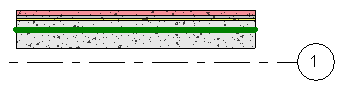
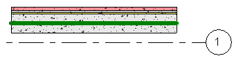
When the Horizontal Projection instance property for a wall is specified as a Center of Element on a vertically compound structural wall, it includes all layers and regions to calculate the center. To place the analytical projection at the center of the wall core, specify the Horizontal Projection as Center of Core.
| Center of element projection |
Center of core projection |
|---|
|
|
|
| Vertical/planar Extensions |
|---|
| Top |
Base |
|---|
| Top of Wall |
Bottom of Wall |
| <Level...> |
<Level...> |
| <Reference Planes...> |
<Reference Planes...> |