Use common sketch tools to define the boundaries for a system of fabric sheets covering an area.
- Click Structure tab
 Reinforcement panel
  (Structural Fabric Area).
 - Select the floor, wall or foundation slab to receive the fabric area.
- Click Modify | Create Fabric Boundary tabDraw panel
 (Boundary Line).
 - Sketch a closed loop.
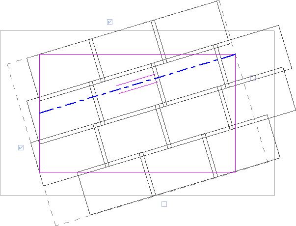
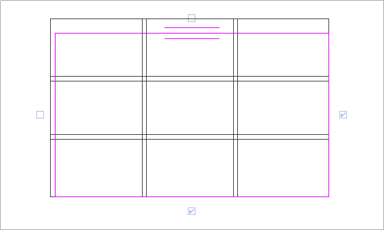 Note: A parallel line symbol indicates the major direction edge of the fabric area. In sketch mode, you can change the major direction of this area. The major direction of fabric area is very important because it determines the fabric sheet rotation. Major wire within the fabric sheet is parallel to the major direction. Each fabric area has a rectangular envelope (dashed line) with edge controls.
 - Select the controls to determine the starting/ending edges of the fabric sheet layout.
Using these controls you indicate the fabric sheet alignment and lap-splice values. You should select at least 2 neighboring controls to create a correct fabric sheet layout. The fabric sheet layout adjusts fabric sheets to the fabric boundary. The fabric sheet is cut by the sketched boundary and openings in the host.
 Note: To change the graphic parameters of fabric reinforcement, click View tabGraphics panel
  (Visibility Graphics) and modifying parameters under Structural Fabric Areas or Structural Fabric Reinforcement.
 - Select the lap-splice position in the Construction section of the Fabric Area Properties palette.
- Click Modify | Create Fabric Boundary tabMode panel
 (Finish Edit Mode).
 - To place symbols and tags automatically on the completed sketch, select the correct view in the Tag new member in view parameter under Identity Data of the Fabric Area Properties palette.
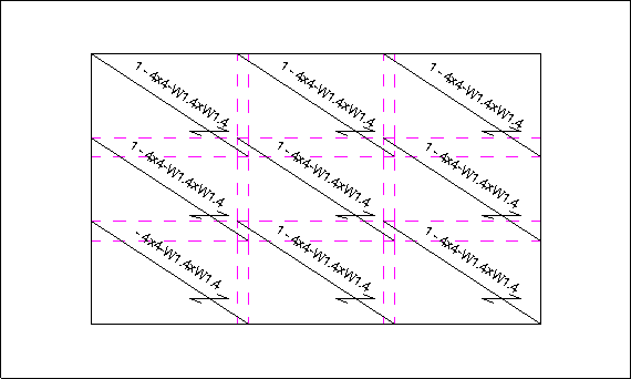
Revit places a fabric reinforcement symbol and tag for each fabric sheet separately.