Use the Pipes Only option when you want to lay out a pressure network without inserting bends when the direction of pressure network changes. This option can be used to create deflection for pressure network parts with allowable deflection angles. You can also use curves to represent flexible curved pipe or deflected, non-flexible pipe.
- On the Prospector tab in the Toolspace, right-click Pressure Networks and select Create Pressure Pipe Network by Layout.
- Use the Create Pressure Network dialog box to specify the pressure network name, the parts list, reference objects, layers, and label styles.
- Click
OK to display the
Pressure Network Plan Layout ribbon.
Click Pipes Only
 . You are prompted at the command line to specify the first point or enter an elevation.
Note: If you specify a reference surface and Cover value, then the surface elevations and cover value are used to establish the pressure network elevations during the pressure network layout. You can also enter an elevation for the start point (the elevation of the first point specified), which would override the elevation determined by the reference surface and cover. This can be helpful when a design is connecting to an existing network of a known elevation.
. You are prompted at the command line to specify the first point or enter an elevation.
Note: If you specify a reference surface and Cover value, then the surface elevations and cover value are used to establish the pressure network elevations during the pressure network layout. You can also enter an elevation for the start point (the elevation of the first point specified), which would override the elevation determined by the reference surface and cover. This can be helpful when a design is connecting to an existing network of a known elevation. - On the Network Settings panel on the ribbon, verify that the desired reference surface is selected and that the Cover value is set to the value required for your project.
- On the Layout panel on the ribbon, specify the size and material for the pressure network pipes.
- Begin selecting points in the drawing. Draw straight segments to insert straight pipe segments, or enter
C for Curve to draw a curved segment. For more information, see
To Insert Curved Pressure Network Segments.
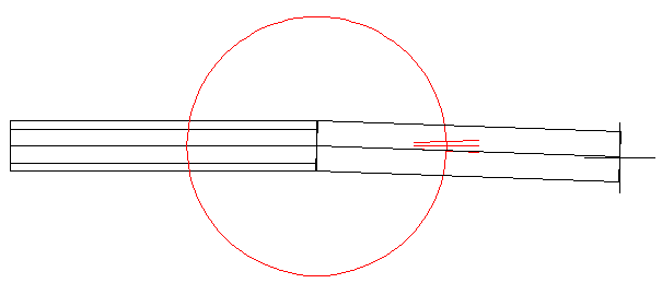
After you select two points to insert the first pressure pipe, the compass is displayed and shows the allowable deflection angles at which you can insert the next pipe (based on the allowable deflection defined in the parts list for the selected pipe size and material).
The allowable deflection for the pressure pipe shown in the following illustration is 2 degrees.
- To insert the next pressure pipe at a deflected angle, move the cursor so it is at the desired length and so that the angle is aligned close to one of the angles on the compass. The deflection angle closest to the location you click is snapped to and the part is inserted.
Note: During layout, or when using the Continue Layout grip, a single pressure pipe is created when multiple connected segments are drawn in a straight line with no horizontal or vertical directional changes.
- Continue laying out the pressure network and press Enter to end the command.