Use the Pipes & Bends option when you want to lay out a pressure network and insert bends when the direction of the pressure network changes. You can also use curves to represent flexible curved pipe or deflected, non-flexible pipe.
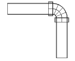
Bend angles are measured relative to the direction of the last pipe drawn.
- On the Prospector tab in the Toolspace, right-click Pressure Networks and select Create Pressure Pipe Network by Layout.
- Use the Create Pressure Network dialog box to specify the pressure network name, the parts list, reference objects, layers, and label styles.
- Click
OK to display the
Pressure Network Plan Layout ribbon.
The Pipes & Bends
 option is selected by default. You are prompted at the command line to specify the first point or enter an elevation.
Note: If you specify a reference surface and Cover value, then the surface elevations and cover value are used to establish the pressure network elevations during the pressure network layout. You can also enter an elevation for the start point (the elevation of the first point specified), which would override the elevation determined by the reference surface and cover. This can be helpful when a design is connecting to an existing network of a known elevation.
option is selected by default. You are prompted at the command line to specify the first point or enter an elevation.
Note: If you specify a reference surface and Cover value, then the surface elevations and cover value are used to establish the pressure network elevations during the pressure network layout. You can also enter an elevation for the start point (the elevation of the first point specified), which would override the elevation determined by the reference surface and cover. This can be helpful when a design is connecting to an existing network of a known elevation. - On the Network Settings panel on the ribbon, verify that the desired reference surface is selected and that the Cover value is set to the value required for your project.
- On the Layout panel on the ribbon, specify the size and material for the pressure pipes. The pipes and bends will share the same material and nominal diameter.
- Begin selecting points in the drawing. Draw straight segments to insert straight pipe segments, or enter
C for Curve to draw a curved segment. For more information, see
To Insert Curved Pressure Network Segments.
After you select two points to insert the first pressure pipe, the compass appears and displays the angles of bends in the parts list that match the selected size and material.
For example, in the illustration below, the compass shows that 11.25, 22.5, and 90 degree bends are available. A 22.5 degree bend will be inserted into the drawing if the pointing device is clicked in the current position.
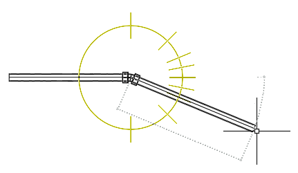
- To insert a bend, click an angle close to one of the angles on the compass. The bend angle closest to the location you click is snapped to and inserted.
Note: During layout, or when using the Continue Layout grip, a single pressure pipe is created when multiple connected segments are drawn in a straight line with no horizontal or vertical directional changes.
- Continue laying out the pressure network and press Enter to end the command.