The compass is a guide which you can use during pressure network layout to insert the next pressure network part. The compass appears as a circle and tick marks after the first pipe segment is drawn. The tick marks show the angles that can be established with the available bends or the allowable deflection angles.
When the Pipes & Bends command is active, the compass displays the angles of bends in the current parts list that match the selected pipe size and material.
For example, in the illustration below, the compass shows that 11.25, 22.5, and 90 degree bends are available. This means that for the selected pipe size and material, there are also 11.25, 22.5, and 90 degree bends defined for that same material and nominal diameter in the current parts list.
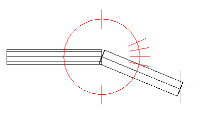
The compass constrains your selections to these available angles. The angle that your cursor is closest to when you click to establish the next point in the pressure network is snapped to. For example, a 22.5 degree bend will be inserted into the drawing if the pointing device is clicked in the current position.
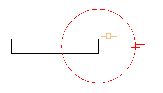
When the Pipes Only command is active, the compass displays the allowable deflection angles for the selected pipe size and material.
The allowable deflection for the pipe shown in the following illustration is 2 degrees.
If you select a different pipe size and material during layout, the compass tick marks are updated to display the angles of the bends or the allowable deflection angles for the current pipe size and material.
You can adjust the compass settings on the Compass ribbon panel, including turning it off and on, on the Pressure Network Plan Layout ribbon.
To use the compass
- When a layout command is active (including when a Continue Layout grip is selected) the compass displays the angles of the bends or the allowable deflection angles for the current pipe size and material. Move your cursor to snap to one of the available angles, and then click your cursor to establish the next pressure network segment in the drawing.
Compass Behavior in Profile View
The compass is not displayed in profile view. However, the insertion of parts is constrained to available angles when using the Pipes & Bends option in profile view, and a guide is displayed which shows the angle that is being snapped to. For more information, see To Add Pressure Network Parts in Profile View.Compass Behavior in Model View
- Compass 3D Plane: Specifies the increment by which the working plane is rotated in model view. When you are working in model view to create or edit a pressure network, and the compass is visible, you can use the following keyboard shortcuts to control the compass plane:
- Enter
P to rotate the compass plane in increments equal to the value of the
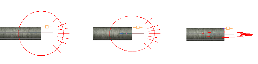
Compass 3D Plane increment setting. The first image below shows the compass as it appears when the continue layout grip is selected on the pressure pipe. The second image shows the compass after
P is entered once. The third image shows the compass after
P is entered a second time.
- Enter Shift+P to rotate the compass in the reverse direction.
- Enter R to restore the compass to the initial plane setting.
Note: When you are adding parts to the pressure network using a rotated compass plane, the ViewCube changes to display the plane that the next part is to be placed on. The view of the compass plane may also change as you add parts because the plane is adjusted with respect to the next part to be drawn. - Enter
P to rotate the compass plane in increments equal to the value of the
Compass 3D Plane increment setting. The first image below shows the compass as it appears when the continue layout grip is selected on the pressure pipe. The second image shows the compass after
P is entered once. The third image shows the compass after
P is entered a second time.
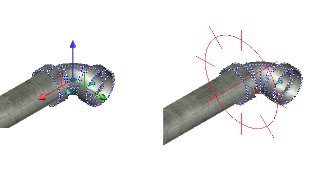
- Compass 3D Snap: Specifies the increment by which fittings and appurtenances can be rotated in model view using the compass. This increment setting applies to the compass when invoked with the rotation grip on fittings and appurtenances in model view. When you are working in model view, you can click the rotation grip to activate the grip and the compass. The
Compass 3D Snap setting controls the spacing between the compass tickmarks when the rotate grip is selected.
 Note: The compass 3D Plane keyboard shortcuts do not work with the rotate grip compass.