You can add or modify the frequency of stations in a corridor region using the EditCorrRegionFreq command.
Station frequency can be specified by referencing portions of the existing alignment and profile geometry in a region.
For example, you can specify assembly insertion frequency for the following components of a corridor region:
- Along tangents. Specify the assembly insertion frequency along the tangent portion of an alignment.
- Along curves. Specify the assembly insertion frequency along the curve portion of an alignment.
- Along spirals. Specify the assembly insertion frequency along the spiral portion of an alignment.
- Along profile curves. Specify the assembly insertion frequency along the curve portion of the profile.
- At specific points. Specify whether assemblies should be inserted at specific geometry points, including horizontal geometry, superelevation critical, profile geometry, and profile high and low points.
- Along offset targets. Specify whether assemblies should be inserted based on offset targets.
You can also modify station location and frequency by manually adding stations.
Inserting Assemblies Adjacent to the Offset Target Start and End Points
To better reflect the corridor geometry where offset targets start and end, you can choose to insert assemblies using the Adjacent To Offset Target Start/End option in the Frequency To Apply Assemblies dialog box. This setting creates stations at a small distance before an offset target start and after an offset target end.
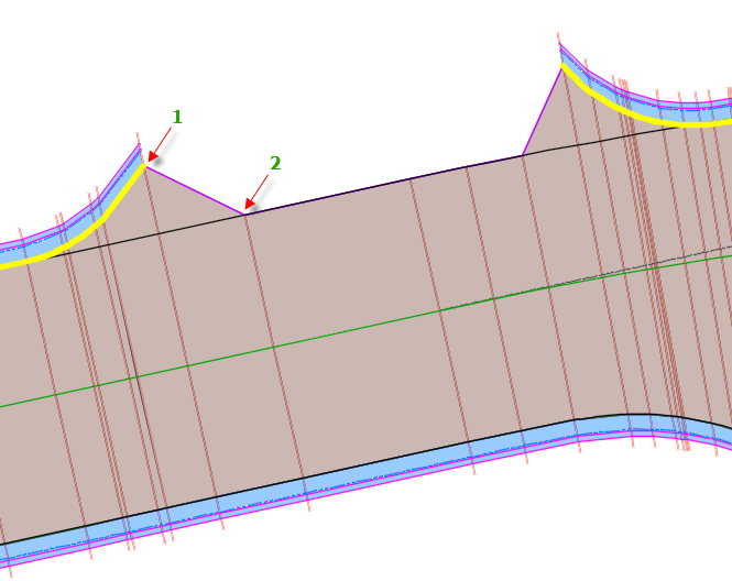
Results When Adjacent To Offset Target Start/End Setting Is Set to No
The following example shows how corridor geometry is created where there is a gap in the offset target when this setting is set to No. Note how the station at the offset target end ("1" in the illustration below) is connected to the next adjacent station on the corridor ("2" in the illustration below)
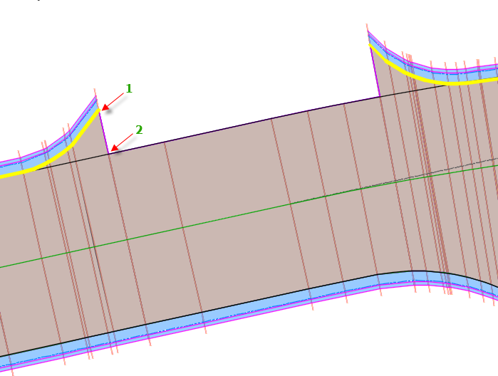
Results When Adjacent To Offset Target Start/End Setting Is Set to Yes
To more accurately represent this area, you can set the Adjacent To Offset Target Start/End setting to Yes. When this setting is set to Yes, the corridor area is created as shown in the following illustration. The offset target end ("1" in the illustration below) is now connected to the new station on the corridor ("2" in the illustration below) that was added at a small distance after the offset target end station location. At this magnification level, the new station location is not visible.
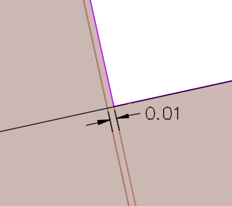
The following illustration shows a detail of the new station location ("2" in the illustration above) that was added adjacent to the end station. The offset target end links to the new station that was created at a distance of .01 units away from the offset target end, resulting in a more accurate representation of the corridor geometry.
The stations that are added with the Adjacent To Offset Target Start/End setting are dynamic and will be updated if edits are made to the offset target.