Create a freeform box, plane, cylinder, sphere, torus, quadball or face. You can also convert BREP geometry.
Important: The Freeform panel is converted to a ribbon tab when you enter the freeform environment. The ribbon path for the commands shown in the following sections is the entry point for the freeform environment. After you enter the freeform environment, all freeform geometry create commands are located here: Freeform tab  Create panel command name.
Create panel command name. Create a Freeform Box
The freeform Box command creates a rectangular body on a work plane or planar face.
- Click 3D Model tab Freeform panel Box
 .
. - Click a work plane, planar face, or 2D sketch.
- Click in the graphics window to specify the base point of the box.
- Change and adjust the shape by:
- Using the manipulators to adjust length, width, and height in the graphics window.
- Changing the Length, Width, and Height in the Box dialog box.
- Changing the number of Faces for the length, width, or height in the Box dialog box.
Tip: The more faces you add, the more you can manipulate the shape. - To add symmetry, select any of the following:
- Length Symmetry. Enables symmetry on the length of the box.
- Width Symmetry. Enables symmetry on the width of the box.
- Height Symmetry. Enables symmetry on the height of the box.
- Change the size and direction by:
- Selecting and moving the arrows in the graphics window.
- Changing the Direction in the Box dialog box.
Create a Freeform Plane
Creates a rectangular freeform plane on an origin plane, a work plane, or a planar face.
- Click 3D Model tab Freeform panel Plane
 .
. - Click an origin plane, work plane, planar face, or 2D sketch.
- Click in the graphics window to specify the base point of the plane.
- Change and adjust the shape by:
- Using the manipulators to adjust length and width.
- Changing values for the length and width in the input fields.
- Changing the number of faces in the length and width direction. Tip: The more faces you add, the more you can manipulate the shape.
- Add symmetry in the length and width directions by selecting the respective checkbox in the Plane dialog box.
- Change the size by entering a value for length or width, or by moving the arrows in the graphics window.
- Click OK.
Create a Freeform Cylinder
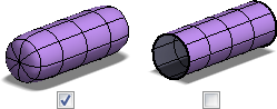
The freeform Cylinder command defines a cylindrical body by adding depth to a circular region.
- Click 3D Model tab Freeform panel Cylinder
 .
. - Click a work plane, planar face, or 2D sketch.
- Click in the graphics window to specify the base point of the cylinder.
- Change and adjust the shape by:
- Using the manipulators to adjust the radius and height in the graphics window.
- Changing Radius and Height in the Cylinder dialog box.
- Changing the number of Faces for the radius or height in the Cylinder dialog box.
Tip: The more faces you add, the more you can manipulate the shape. - To add symmetry, select any of the following:
- X Symmetry. Enables symmetry along the X axis.
- Y Symmetry. Enables symmetry along the Y axis.
- Z Symmetry. Enables symmetry along the Z axis.
- Check Capped to create a closed cylinder body. Clear the checkbox to create an open cylinder body.
- Change the size and direction by:
- Selecting and moving the arrows in the graphics window.
- Changing the Direction in the Cylinder dialog box.
- Click OK.
Create a Freeform Sphere
- Click 3D Model tab Freeform panel Sphere
 .
. - Click a work plane, planar face, or 2D sketch.
- Click in the graphics window to specify the center point of the sphere.
- Change and adjust the shape by:
- Using the manipulators to adjust the radius in the graphics window.
- Changing the Radius in the Sphere dialog box.
- Changing the number of Faces for the Longitude (around the sphere) and Latitude (up and down the sphere) in the Sphere dialog box.
Tip: The more faces you add, the more you can manipulate the shape. - To add symmetry, select any of the following:
- X Symmetry. Enables symmetry along the X axis.
- Y Symmetry. Enables symmetry along the Y axis.
- Z Symmetry. Enables symmetry along the Z axis.
- Click OK.
Create a Freeform Torus
- Click 3D Model tab Freeform panel Torus
 .
. - Click a work plane, planar face, or 2D sketch.
- Click in the graphics window to specify the center point of the torus.
- Change and adjust the shape by:
- Using the manipulators to adjust the radius in the graphics window.
- Changing the Radius of the inner circle of the torus and the Ring size of the torus in the Torus dialog box.
- Changing the number of Faces for the Longitude (around the torus) and Latitude (up and down the torus) in the Torus dialog box.
Tip: The more faces you add, the more you can manipulate the shape. - To add symmetry, select any of the following:
- X Symmetry. Enables symmetry along the X axis.
- Y Symmetry. Enables symmetry along the Y axis.
- Z Symmetry. Enables symmetry along the Z axis.
- Click OK.
Create a Freeform Quadball
- Click 3D Model tab Freeform panel Quadball
 .
. - Click a work plane, planar face, or 2D sketch.
- Click in the graphics window to specify the center point of the quadball.
- Change and adjust the shape by:
- Using the manipulators in the graphics window.
- Changing the Radius in the Quadball dialog box.
- Changing the number of Faces on a span edge in the Quadball dialog box.
Tip: The more faces you add, the more you can manipulate the shape. - To add symmetry, select any of the following:
- X Symmetry. Enables symmetry along the X axis.
- Y Symmetry. Enables symmetry along the Y axis.
- Z Symmetry. Enables symmetry along the Z axis.
- Click OK.
Convert BREP geometry to a freeform object

Converts normal BREP (boundary representation) geometry into a freeform object and retains the original geometry.
- Open a 3D surface or solid model.
- Click 3D Model tab Freeform panel Convert
 .
. - Select the faces to convert to freeform.
- Specify the number of Length and Width faces. If the preview image indicates that the freeform shape is different from the original, increase the number of faces.
- Click OK.
- Use the editing tools in the freeform environment to manipulate the shape.
Note: Trimmed planar faces are converted as untrimmed faces.
Create a Freeform Face
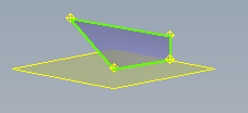
A Face can be created as a sheet body, or it can be used to close gaps in an existing body. When you create a face, vertex selections are planar unless you select reference geometry, such as existing vertices or work points.
Note: Smooth mode is off when you select points to create a face. 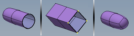
- Click 3D Model tab Freeform panel Face
 .
. - Specify the Mode option. Choose Simple to select each vertex. Choose Edge to select an Edge and then select two points to finish the face.
- Specify the Sides option. Choose Four sides to define a face with four corners. Choose Multiple to define a face with any number of points greater than three. To close the face pick the first point specified.
- Click Done to finish.
Tip: You can use a Freeform Face to close gaps in a body