In the typical design process, a PCB designer lays out the components on a board. Then the completed board assembly passes through the IDF to the mechanical designer to verify fit (size, shape, height) in the context of an existing assembly.
Another common workflow involves the design of PCB boards to be used as standard components in other assemblies, or as stand-alone parts or assemblies.
To accommodate these common workflows, the IDF Translator provides two ways to import IDF data:
- Import the data as a new part or assembly file.
- Place the data as a component in an existing assembly in Autodesk Inventor.
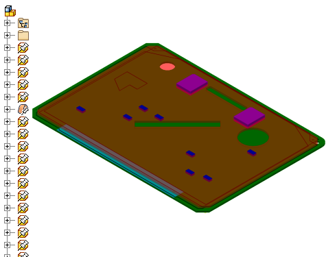
When imported as an assembly document, the board components are translated into multiple parts that are contained in the new assembly. Each part file contains the data for one or more component instance. The following illustration shows the results of importing the idf.brd file in the browser.

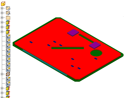
When imported as a part document, the board components are translated into the sketches and extrusions that make up the part model in a hierarchy. Importing IDF data as a single part simplifies file management. It reduces the number of files that must be opened to display an accurate representation of the PCB assembly.
