Cable structures are structures with cables as the main load-carrying elements. If one of the main dimensions of an element is bigger than the two remaining ones, and section rigidity with respect to bending and torsion is small in comparison to tension rigidity, such an element is regarded to be a cable.
The basic conclusion drawn from the previous definition is that only tensile forces can be applied to cables. However, in some cases small bending or torsional moments and shearing forces can be applied to cables. The most significant advantage of using cable structures is the fact that cables have great admissible tensile stresses.
Therefore, you can use a cable section in such a way that you can design light, economical and aesthetic structures. There are 2 advantages of using cable elements in designed structures:
- Entering the initial cable tension regulates the internal force and makes the results more effective.
- Simple assemblage (such as, suspension and assemblage of an entire structure, because of its lighter weight).
The theory of cable structures is based on the following assumptions:
- Loads and other external effects are of quasi-static type and constant in time
- For cables no bending moments and shearing forces are considered
- Cable elements work in the elastic range (Young's modulus E = const)
- Any loads can be applied, except for moment loads
- Large displacements u, but small gradients du/dx are allowed
- Cable section area F is constant (F=const)
- Unloaded cable length = l
Equations governing the problem
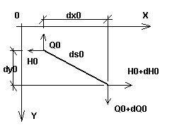
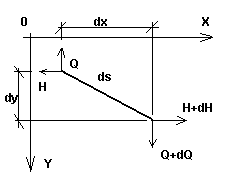
Let us consider a small sag cable (that is, a cable for which the angle between the tangent in any cable point and a straight line joining its ends is small), loaded with an arbitrary load in its plane. Let us consider an infinitesimal element in this cable, which is described in the initial stage (first, assembly stage) by the load q0, temperature T0, and tension H0; the length of this element is equal to dso (Fig. 1a). After the load is applied to the cable (second, final stage with the load q, temperature T and tension H), the length of an elementary cable section equals ds (Fig.1b). Both stages, together with the loads in both planes (xy and xz) are displayed also in Fig. 2.
 Fig.1a |
 Fig.1b |
Assuming a small cable sag value and taking into account that the total cable force must be tangent to the cable, you can assign the appropriate cable elongation as a function of only static values. After the integration along the total cable length is done, the known formula for a cable with a small cable sag value is obtained. The cable chord elongation value D can be derived from (1).

Fig. 2

where:
A, B - Beginning and end cable node
EF - Cable tension rigidity (where: E - Young's modulus, F - cable cross section area)
a - Coefficient of thermal expansion
l - Initial cable length (for unloaded cable)
D - Distance change between supports
d - Initial, internal cable shortening/elongation (regulation)
DT - Change in temperature
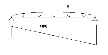
Q(x) - Function of shear force as for a beam with pinned supports (according to indexes: respectively in the Y-axis and Z-axis directions and for the initial and final stage). See Fig. 3a.

Fig. 3a
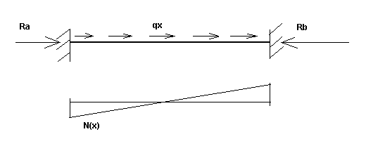
N(x) - Axial force function caused by the static load for a beam with fixed supports (during the initial or final stage). See Fig. 3b.

Fig. 3b
You can also notice that in the cable equation (1), as opposed to traditional solutions applied to cable calculations, axial force can vary along the cable's length (in denominators of both integration functions in the equation (1) the following functional components exist: [H+N(x)] 2 and [H0+N0(x)] 2 ). It allows for more accurate results.
See also: