Cable element theory in Robot is based on the general theory of cables with a small value of cable sag. According to this theory, cable rigidity is an implicit function of the following parameters: cable tension rigidity (E*F), cable tension, cable support displacements, and transverse loading in both directions (p y , p z ).
Because of the non-linearity of the cable element, its definition in the structure requires applying iterative methods of structure analysis.
Cable implementation capabilities in Robot:
- Cable elements can be used together with elements of the following structure types: PLANE FRAME, SPACE FRAME, and SHELL.
- All standard structure analysis types are allowed: Linear (in fact, it is a non-linear analysis, but no other non-linear effects, except that the non-linearity of cable elements is considered), Non-linear (with regard to stress-stiffening effect), P-Delta, Incremental, Buckling, Dynamic, Harmonic, and Seismic. Note: Dynamic analysis is treated as linear with regard to the current rigidity.
- Offsets are allowed.
- Material is defined as for a bar (Young's modulus E is the only requirement in the case of a cable dead load definition, additionally, the unit weight, RO, should be entered, and in the case of a thermal load, the coefficient of thermal expansion LX)
- GAMMA angles defined as for bars (it is substantial only for the load description).
Limitations:
- For cable elements, a release definition is impossible, because bending and torsional rigidity do not apply to such elements.
Cable loads
The following load types apply to cable elements:
- Nodal loads
- Dead loads
- Uniform loads (constant or variable)
- Initial shortening/elongation (additional loads applied during the assembly stage)
- Temperature load
- Concentrated forces along the element's length.
The following load types do not apply to cable elements:
- Moment
- Uniform moment
SYNTAX (to be entered by a user in a text file)
PROperties
(<element list>) CABles AX=<section area> (E=<Young's modulus>)
(RO=<unit weight>) [STRess = <s> | FORce = <h> | LENgth = <l>
| [ DILatation = <d> (RELative) ]]
where:
STRess - Normal stress (calculated in regard to the chord) to be achieved for the assembling load case.
FORce - Tension force (calculated in regard to the chord) to be achieved for the assembly load cases.
LENgth - Initial cable length.
DILatation - Difference between the initial cable length and the distance between the support nodes. (If it is a positive value - the length is bigger than the distance between the nodes; if negative - the length is smaller than the distance between the nodes.)
RELative DILatation - Ratio of the difference between the initial cable length and the distance between the support nodes to the distance between the support nodes. (If it is a positive value - the length is bigger than the distance between the nodes; if negative - the length is smaller than the distance between the nodes.)
- Young's modulus E can be defined in the material definition.
- Keywords: STresses, FORce, LENgth and DILatation are explicitly defined and are not required. If none of these parameters are specified, the initial cable length equals the distance between nodes.
Assembling Load Case
Robot includes the structure assembly stage. It is recommended that this is the first load case. Syntax for such a load case follows:
CASe
ASSembly
[load description]
For this load case:
- For selected bars, the initial tension forces are specified by entering one of the following values in a text file syntax (PROperties command):
STRess = s0 (initial cable stress)
FORce = t0 (initial tension force in the cable)
- The initial cable length can be described by specifying the LENgth = l
0
, if it is to be different from the default value LONG =
 which is equal to the distance between the nodes.
 - The initial cable shortening/elongation can be specified using the DILatation (RELative) command.
- If there is no RELative keyword, DILatation is expressed in absolute values.
- If there is a RELative keyword, the initial elongation is expressed as a fraction, that is, the final cable length equals: L = LONG (1 + DIL).
- All defined loads are applied (such as, dead load, and added masses).
- Temperature TX definition for cables in the assembly stage is allowed .
- Displacements calculated for such a load case describe the initial geometry for the remaining cases in the structure analysis.
During the analysis of successive structure load cases in the state of equilibrium, the assembling case loads applied to the structure are considered. Displacements assigned to this case are used as the basis for further analysis. Predefined tension forces are changed, which means that after the assemblage, the cable is anchored.
Cable equation for the assembly stage
At this stage, equation (1) describes the transition from:
- Unloaded cable (cable lying on the floor):
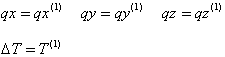
q0x = q0y = q0z = 0 (no load)
H0 = 0 (no cable tension)
T0 = 0
for which the length is equal to L1= :
1.
long, when (long ≠ 0) - if the LENgth value is specified in a cable definition
2.
[distance (A, B) + dilatation], when dilatation is defined in an absolute system - if the DILatation value is specified in a cable definition
3.
[distance (A, B)*(1+dilatation)], when dilatation is defined in a relative system - if the RELative DILatation value is specified in a cable definition
4.
[distance (A, B)], when (dilatation = 0) and (long = 0) - if there is no keyword such as: LEngth, DILatation or RELative DILatation in a cable definition or one of the following keywords: FORce or STRess exists.
to
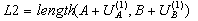
- cable anchored in the structure with all loads of the first (assembling) load case:
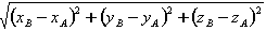
L2 - Distance between support nodes A and B of the deformed cable:
L2 = distance (A+U A , B+U B ),
where:
U A - Displacement of the point A
U B - Displacement of the point B.
Various situations for the first, assembling load case are possible:
- Force H is known (controlled) - if STRess or FORce (tension) is not equal to zero (STRess≠0 or FORce≠0). Then, the tension force equals:

From the equation (1):
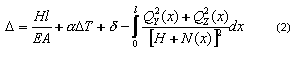
l value is the distance between the beginning and end node of the cable.
From the equation (2) one can assign the initial cable elongation d essential for obtaining the required force H:
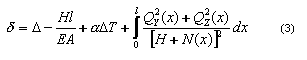
- Tension force H is unknown (neither the STRess nor the FORce values are given in the cable syntax), then:
- If the displacements during the assembly stage are considered (defined by entering the LENgth, DILatation or RELative DILatation values in the cable syntax), that is,
then, solving the equation (4) according to the force H

and iterating through the system of equations, the final value of the assembling force is found.
It is equal to:
 .
. - If no nodal displacements are considered, that is,
L2 = length (A, B)
solving the equation (4) the initial value of the force required for the cable anchorage between supports is found.
- If the displacements during the assembly stage are considered (defined by entering the LENgth, DILatation or RELative DILatation values in the cable syntax), that is,
- Force H is known (controlled) - if STRess or FORce (tension) is not equal to zero (STRess≠0 or FORce≠0). Then, the tension force equals:
Load cases after anchorage
After completing the structure analysis, results for cable elements are similar to those obtained for bar elements; however, some differences remain. The differences include:
- No shearing forces and moments can be obtained for cable elements,
- For cable elements either the simplified deformation (assigned as for the truss bar) or the exact deformation (described by the differential equation of the sag line) can be obtained
- Additional results for cable elements (as a result of the assembly stage):
- In cables for which tension is required (in the Robot syntax: STRess or FORce), the regulation value [m] needed for the required tension is assigned
- In other cables, the force essential for assemblage is assigned
Such results are useful for designing the assembly stage. They are available from the Results module by selecting the command: Stresses > Parameters > Results for the cable elements in the assembly stage.
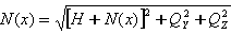
- Axial force (tensile) is calculated from the formula:
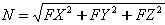
where:
N - Force applied along the cable tangent
FX, FY, FZ - N force components projected on directions of successive axes of the local coordinates system
Cable equation during the cable's work in the structure
When an arbitrary case (i) is defined after the first assembling case, cable behavior is obtained by solving the equation (1). Iteration of such an equation is run according to the following assumptions:
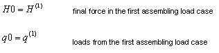

![]() Load from the first load case is automatically added to the load in the (i) case
Load from the first load case is automatically added to the load in the (i) case
Tension force H is treated as an unknown quantity.
See also: