The following remarks concern the calculations of structures including cables:
- The definition of initial tension forces in cables should be well thought-out. Values of tension forces or stresses specified in a cable definition are the exact values required by the algorithm in the assembly load case within the appropriate cable (measured along its chord). This requirement results in finding the necessary cable length. If tension forces implemented in an isostatic structure are not balanced, then equilibrium cannot be reached.
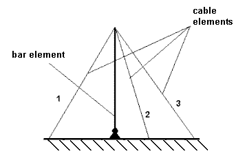
Frequently, a user defines the tension force of a cable less than the load (such as self-weight) acting on it; in such cases it is known that there is no physical solution to this model. A similar problem concerns the static model displayed in the following image.

The model which is displayed can be a model of a whole structure or a part of a larger structure. If in the definition of a cable, random values of the assembly tension forces are assigned to cables numbers 1, 2 and 3, then most likely it will be impossible to fulfill the equilibrium conditions for the horizontal direction (the total for the horizontal components of tension forces from all three cables would need to be equal or close to zero). Therefore, the calculation process for this structure is not convergent or calculation errors occur. Such errors are typical of abnormally large displacements and rotation angles of structure nodes (to fulfill the equilibrium conditions, abnormally large rotation angles are defined in the structure, which frequently results in exceeding the domain of the functions: acos, asin, or root).
Therefore, in the initial stage of calculations, it is best to define cables by specifying the cable length instead of the tension forces. Only after becoming familiar with approximate values of tension forces, can you determine the values of tension forces for reasonable values of cable length, keeping in mind that the equilibrium conditions should be fulfilled at least approximately in nodes similar to those in the model shown in the image above.
A similar situation occurs with collinear chains of cables to which the same values of tension force are assigned. The analysis is not convergent, because tension forces cannot be alike in all the cables because of cable sag.
- Cables show no bending stiffness. For collinear cable chains or cable nets, remember they have no stiffness in the perpendicular direction, especially if the third-order non-linear effects (Pdelta), that is the effect of geometry (shape) modification on structure stiffness, is not considered.
- Because cable elements cause strong non-linearity of the system, in some cases you should:
- Define a higher number of load increments (NDIV>10).
- Apply the Full Newton-Raphson algorithm, which means that the K stiffness matrix should be updated after each load increment and sub-increment.
However, the parameters above should not always be set. In some cases, when solution convergence is achieved even in one load increment, the simplest algorithm (Initial Stress) can be used.
- If cables are defined by specifying their length (using the options: LENgth, DILatation, DILatation RELative, or without any command) and loads are applied to a structure which cause some cables not to work (cannot carry any forces), then the analysis of a cable structure might not reach convergence. To avoid this, the self-weight load should be applied to all cables in the assembly load case. It reflects the actual situation, because real structures do not include cables which do not carry tension, because there is always a slight tension resulting from the cable self-weight.