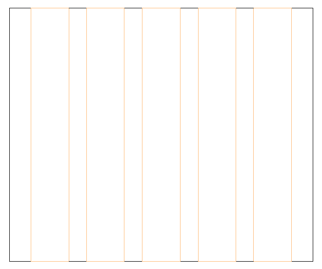
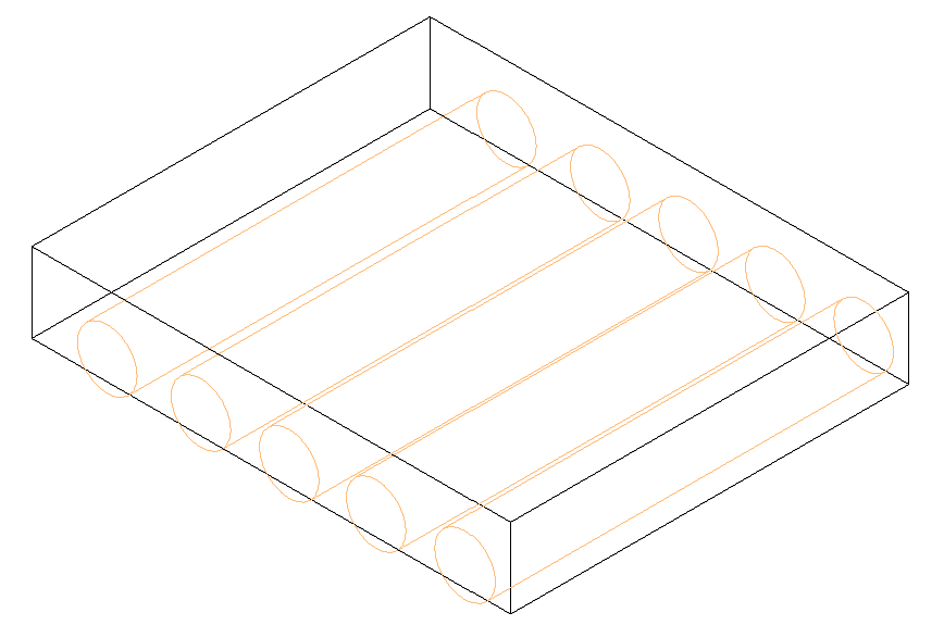
Learn how to model a hollow core type family.
Known issues for hollow core families
- Strands only have one diameter.
- Free form rebar will pass through inner openings.
- Voids do not update when the width of the hollow core slab is modified. To update this geometry, re-split the floor.
- Strand diameters should be more than 5 mm.
- Create a new family using the Metric Generic Model.rft template.
- Open the Front Elevation view.
- Create a new extrusion object: Create tab
 Forms panel
 (Extrusion).
- Use the Draw tools to sketch a rectangle. The rectangle width must be the maximum element width (here 1200 mm) and the rectangle height must be equal to the element height (here 200 mm). The extrusion can have any length (here 1000 mm).

- Click Modify | Create Extrusion tab
 Mode panel
 (Finish Edit Mode). The extrusion is the virtual hollow core element and will now be set up for the hollow core type.
- Select the 3D Top view (the holes are placed on the top face).
- Click Create tab
 Model panel
 (Component). Load the void family, choose the family type, and place the void in the extrusion body to create the hole.


- Select the 3D Front view and correct the horizontal position of the holes by using dimension lines, for example:

- Modify the vertical position of the holes by changing the Position from Top parameter of the holes. In this example the parameter is set at 100 mm (half of the element thickness), to center the holes vertically:

- Define the parameter Valid Widths:
- Click Create tab
 Properties panel
 (Family Types).
- In the family types dialog select, click
 (New Parameter).
- In the Parameter Properties dialog, select Shared Parameter and click the Select button to choose the shared parameter file from the program data folder.
- Select the Valid Widths parameter.
- Close the Shared Parameter dialog and the Parameter Properties dialog.
- Set the Valid Widths parameter for the hollow core types. These are the widths where the element can be cut. You can define any number of intervals in the [from-to] format. All values must be between 0mm and the element width.
Example: [95-225][315-445][535-665][755-885][795-1105].
Note: For the imperial template, the values between brackets should be entered as decimal inches.
- Click Create tab
-
Repeat the previous step to add the CNC Pattern tag parameter. This parameter should be grouped under Data category. This string will be added in the CAM file for the hollow core slab under GenericInfo1.
- If a family type has been created (for example, if the Name box is not empty), make sure that the family type name is the same as the family name.
- Close the dialog and save the family as Hollow Core Slab _XX in the Custom Slabs template folder. The XX represents the thickness of the floor in centimeters.