Add floating curves to build constraint-based alignment geometry for the areas of your design that require maintaining tangency.
![]() Tutorial Exercise: Adding Floating Curves to an Alignment
Tutorial Exercise: Adding Floating Curves to an Alignment
To add a floating curve (from element, radius, through point)
Add a floating curve, defined by a specified radius and angle range, from an existing element to a specified end point.
This curve supports both compound and reverse solutions.
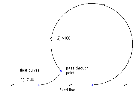
The following illustration shows a floating curve attached to a fixed line and two possible solutions for a given radius and point:
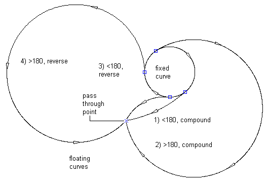
The following illustration shows a floating compound curve attached to a curve and four possible solutions for a given radius and pass-through point. The illustration also shows variables for greater than and less than 180 degrees and compound and reverse variables:
- Click the alignment. Click
 Find.
Find. - On the Alignment Layout Tools toolbar, click
 Floating Curve (From Element, Radius, Through Point).
 - Select the end of the element to which you want to add the floating curve.
- Specify a radius, or enter D to specify the degree of curvature.
Specify a new value, or press Enter to accept the value that is displayed on the command line.
- If the alignment has design criteria applied to it, the minimum value for the current design speed is displayed.
- If the alignment does not have design criteria applied to it, the default value specified in the curve and transition settings is displayed.
Note: To calculate the radius or degree of curvature using other known curve parameters, enter 'CCALC to open the Curve Calculator. - Specify whether the curve solution angle is either greater than or less than 180 degrees. A preview curve is displayed. Note: If the attachment element is a curve, you are prompted to specify either a compound curve or a reverse curve.
- Specify the pass-through point.
To add a floating curve (from element end, through point)
Add a floating curve from the end of an existing element to a specified pass-through point.
The attachment element (1) and pass-through point (2) determine the curve radius. You cannot edit the radius for this type of curve.
The result is a floating curve that is always straight to the element it is attached to.
- Click the alignment. Click Find.
- On the Alignment Layout Tools toolbar, click
 Floating Curve (From Element End, Through Point).
 - Select the end of the element to which you want to add the floating curve.
- Specify the end point. A curve preview is displayed.
To add a floating curve attached (from element end, radius, length)
Add a floating curve element that is defined by the element end to which it is attached, the radius, and the length by specifying the element end where you want to add the curve.
This curve is not defined by a pass-through point, so the entire curve moves with the element to which it is attached.
- Click the alignment. Click Find.
- On the Alignment Layout Tools toolbar, click
 Floating Curve (From Element End, Radius, Length).
 - Select the end of the element to which you want to add the floating curve.
- Specify the curve direction: either clockwise or counter-clockwise.
- Specify a radius, or enter D to specify the degree of curvature.
Specify a new value, or press Enter to accept the value that is displayed on the command line.
- If the alignment has design criteria applied to it, the minimum value for the current design speed is displayed.
- If the alignment does not have design criteria applied to it, the default value specified in the curve and transition settings is displayed.
Note: To calculate the radius or degree of curvature using other known curve parameters, enter 'CCALC to open the Curve Calculator. - Specify the length or [deltaAngle/Tanlen/Chordlen/midOrd/External].
To add a floating curve (from element, through point, direction at point)
Add a floating curve with a specified pass-through point and direction at the pass-through point to an existing element.
The attachment element (1), pass-through point (2), and direction (3) determine the curve attachment point and radius. You cannot edit the radius for this type of curve.
The result is a floating curve that is always straight to the element it is attached to.
- Click the alignment. Click Find.
- On the Alignment Layout Tools toolbar, click
 Floating Curve (From Element, Through Point, Direction At Point).
 - Specify the element to which you want to add the floating curve.
- Specify the end point.
- Specify the direction at the end point or specify quadrant bearing or whole circle bearing.
To create a floating curve by best fit
Add the most probable floating curve through a series of Autodesk Civil 3D points, AutoCAD points, existing elements, or clicks on screen.
The location of the curve start point on the attachment element (1) is determined by the path through the selected regression points (2).
- Click the alignment. Click Find.
- On the Alignment Layout Tools toolbar, click
 Floating Curve - Best Fit.
 - Select an element for the start point and direction.
If you select the beginning of the element, the best fit curve will precede the element. If you select the end of the element, the best fit curve will succeed the element.
- In the Curve By Best Fit dialog box, select one of the following:
- From AutoCAD Points. Select two or more AutoCAD points.
- From COGO Points. Select two or more Autodesk Civil 3D points. Enter G to select a point group or N to enter points by number.
- From Elements. Specify the tessellation and mid-ordinate tolerance settings. Select one or more of the element types listed on the command line. If you selected a profile object, specify the starting and ending station on the Specify Station Range dialog box.
- By Clicking On The Screen. Select at least two points. You can use OSNAP or transparent commands to select points.
As you select points in the drawing window, an X marks each regression point and a temporary, dashed curve is displayed in real time. You must select at least two non-collinear regression points. Press Enter to complete the command.
- In the Panorama window, use the Regression Data vista to make changes to the regression points.
As you highlight a row in the Regression Data vista, the corresponding regression point in the drawing window is highlighted in red.
- Create the curve:
- Click
 to create the curve and keep the Regression Data vista open.
 - Click
 to create the curve and close the Regression Data vista.
- Click