Add free curves to build constraint-based alignment geometry for the areas of your design that require maintaining tangency.
These element types are very similar to the AutoCAD FILLET command, but give you added control.
![]() Tutorial Exercise: Adding Free Curves and Transitions to an Alignment
Tutorial Exercise: Adding Free Curves and Transitions to an Alignment
To add a free curve fillet (between two elements, radius)
Add a free curve, with a specified angle range and radius, between two elements.
This element is defined by the attachment elements (1, 2), radius (3), solution angle, and whether the required solution is compound or reverse. The solution can vary greatly, depending on how you define the constraints.
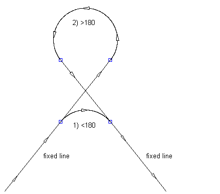
The following illustration shows a free curve fillet between two fixed lines. There are two solutions based on the included angle of the curve:
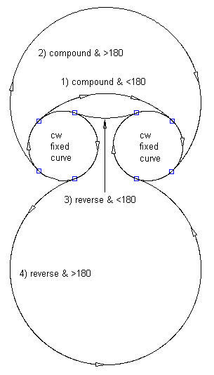
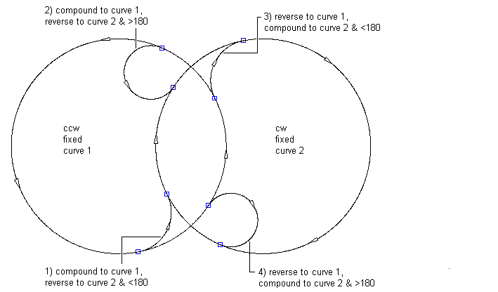
The following illustration shows a free curve fillet between two fixed clockwise curves:
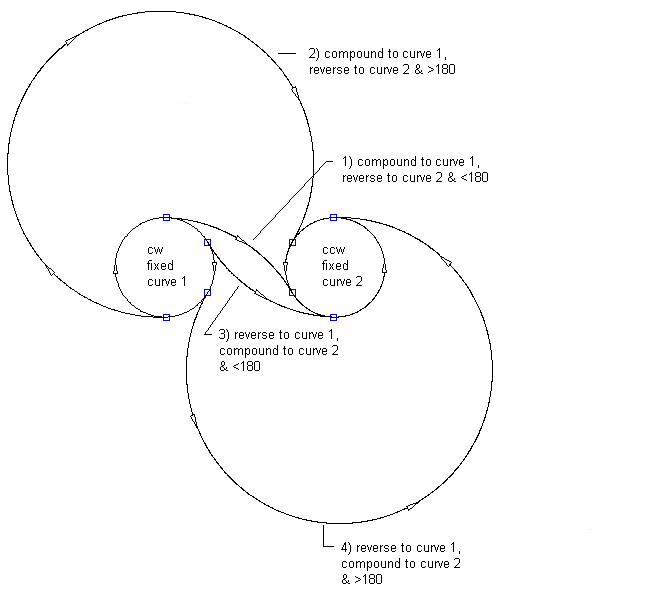
The following illustration shows a free curve fillet between a fixed clockwise curve and a fixed counter-clockwise curve:
The following illustration shows a free curve fillet between an overlapping clockwise curve and a counter-clockwise curve:
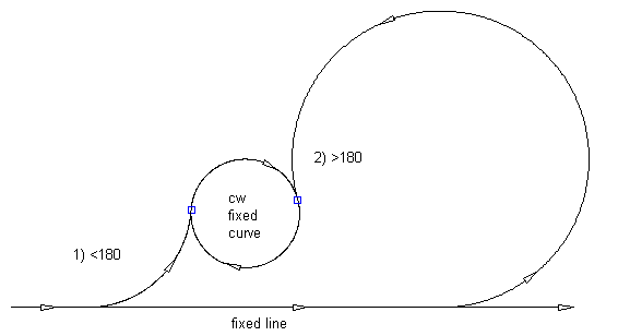
The following illustration shows a free curve fillet between a line and a clockwise curve (on the left) with a specified radius:
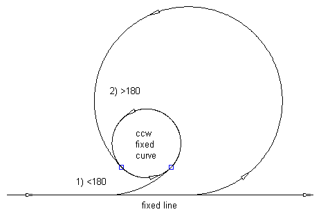
The following illustration shows a free curve fillet between a line and a counter-clockwise curve (on the left) with a specified radius:
- Click the alignment. Click
 Find.
Find. - On the Alignment Layout Tools toolbar, click
 Free Curve Fillet (Between Two Elements, Radius).
 - Specify the element (line, curve) from which you want to add the free curve.
- Specify the element (line, curve) to which you want to add the free curve. Note: The element before and the element after must have the same direction.
- Specify whether the curve solution angle is either greater than or less than 180 degrees.
- Specify the radius or [curveLen/Tanlen/Chordlen/midOrd/External/Degree of curvature].
Specify a new value, or press Enter to accept the value that is displayed on the command line.
- If the alignment has design criteria applied to it, the minimum value for the current design speed is displayed.
- If the alignment does not have design criteria applied to it, the default value specified in the curve and transition settings is displayed.
Note: To calculate the radius or degree of curvature using other known curve parameters, enter 'CCALC to open the Curve Calculator.To display a curve preview you must pick a point in the drawing or enter a coordinate value, then a rubber band is drawn to the cursor from the selected point and the curve preview is displayed.
- Specify the second point. You can enter a 2D coordinate point or use a transparent command.
To add a free curve fillet (between two elements, through point)
Add a free curve, with a specified pass-through point, between two elements.
You can add this element between two lines, two curves, or a line and a curve. The attachment elements (1, 2) and pass-through point (3) determine the curve radius and length. You cannot edit the radius and length for this type of curve.
- Click the alignment. Click Find.
- On the Alignment Layout Tools toolbar, click
 Free Curve Fillet (Between Two Elements, Through Point).
 - Select the element from which you want to add the free curve.
- Select the element to which you want to attach the free curve. A curve preview is displayed.
- Specify the pass-through point. You can enter a 2D coordinate point or use a transparent command.
To create a free curve by best fit
Add the most probable free curve between two elements through a series of Autodesk Civil 3D points, AutoCAD points, existing elements, or clicks on screen.
The location of the curve start and end points on the attachment elements (1,2) is determined by the path through the selected regression points (3).
- Click the alignment. Click Find.
- On the Alignment Layout Tools toolbar, click
 Free Curve - Best Fit.
 - Select the element from which you want to attach the free curve (the First Element).
- Select the element to which you want to add the free curve (the Next Element). Note: The element before and the element after must have the same direction.
- In the Curve By Best Fit dialog box, select one of the following:
- From AutoCAD Points. Select one or more AutoCAD points.
- From COGO Points. Select one or more Autodesk Civil 3D points. Enter G to select a point group or N to enter points by number.
- From Elements. Specify the tessellation and mid-ordinate tolerance settings. Select one or more of the element types listed on the command line. If you selected a profile object, specify the starting and ending station in the Specify Station Range dialog box.
- By Clicking On The Screen. Select one or more points on screen. You can use OSNAP or transparent commands to select points.
As you select points in the drawing window, an X marks each regression point and a temporary, dashed curve is displayed in real time. Press Enter to complete the command.
- In the Panorama window, use the Regression Data vista to make changes to the regression points.
As you highlight a row in the Regression Data vista, the corresponding regression point in the drawing window is highlighted in red.
- Create the curve:
- Click
 to create the curve and keep the Regression Data vista open.
 - Click
 to create the curve and close the Regression Data vista.
- Click