Use this dialog box to add chainages to a corridor.
You can specify the frequency and placement settings for stations along the corridor.
The properties table displays the following settings:
Corridor Information
Displays general information about the corridor.
- Corridor Name
-
Displays the corridor name.
- Baseline Name
-
Displays the corridor baseline (alignment) name.
- Start Station
-
Displays the value for the first chainage for the current assembly region.
- End Station
-
Displays the value for the last chainage for the current assembly region.
Horizontal Baseline
- Along Tangents
-
Specifies the assembly insertion frequency along the straight portion of a horizontal baseline. Enter a value or click
 and select a distance in the drawing.
- Along Curves
- Specifies how the frequency for inserting assemblies along curves is determined.
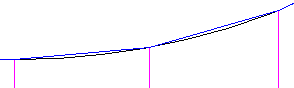
- By Curvature: Horizontal baseline curves are tessellated using the Mid-Ordinate Distance to Define Curvature value. Stations are created along the tessellated curve at each point where the tessellation touches the curve, as shown in the following illustration:
- At an Increment: Stations are placed along the curve at the value specified in the Curve Increment field.
- Both: Uses both the By Curvature option and the At an Increment option.
- By Curvature: Horizontal baseline curves are tessellated using the Mid-Ordinate Distance to Define Curvature value. Stations are created along the tessellated curve at each point where the tessellation touches the curve, as shown in the following illustration:
- Curve Increment
-
Specifies the assembly insertion frequency along the curve portion of a horizontal baseline. Enter a value or click
and select a distance in the drawing. This field is not editable if By Curvature is selected as the Along Curves setting.
- Mid-Ordinate Distance to Define Curvature
- Specifies the value to define the mid-ordinate distance by which to tessellate horizontal baseline curves. This field is not editable if At an Increment is selected as the Along Curves setting.
- Along Spirals
-
Specifies the assembly insertion frequency along the transition portion of an alignment. Enter a value or click
and select a distance in the drawing.
Note: This setting is not used when a feature line is specified for the horizontal baseline. - At Horizontal Geometry Points
-
Specifies whether the assembly should be inserted at horizontal baseline geometry points where the horizontal baseline geometry changes (such as the start of a curve).
- At Superelevation Critical Points
-
Specifies whether the assembly should be inserted at superelevation critical points (such as ‘end normal crossfall’, ‘level crossfall’, ‘reverse crossfall’ and ‘begin full super’).
Note: This setting is not used when a feature line is specified for the horizontal baseline.
Vertical Baseline
- Along Vertical Curves
-
Specifies the assembly insertion frequency along curve portions of the profile geometry. Enter a value or click
and select a distance in the drawing.
Note: This setting is not used when a feature line is specified for the vertical baseline. - At Vertical Geometry Points
-
Specifies whether the assembly should be inserted at vertical baseline geometry points where the vertical baseline geometry changes.
- At High/Low Points
-
Specifies whether the assembly should be inserted at the high and low points of the vertical baseline geometry.
Offset Target
- At Offset Target Geometry Points
-
Specifies whether or not to automatically add assemblies based on offset target objects (feature lines, alignments or polylines).
Note: If both an assembly frequency setting that references horizontal geometry and a setting that references vertical geometry apply to a portion of a corridor, the setting that results in a smaller interval is used. For example, if a segment is both a horizontal straight and a vertical curve, and the vertical curve frequency adds assemblies at more frequent intervals, the frequency specified for vertical curves is used. - Adjacent to Offset Target Start/End
- Specifies whether the assembly should be inserted adjacent to the offset target start and end. This setting creates stations at a small distance before the offset target start and after the offset target end, rather than creating the stations exactly at the offset target start and end. For more information, see About Changing the Frequency of Stations in a Corridor Region.
- Along Offset Target Curves
- Specifies how the frequency for inserting assemblies along offset target curves is determined.
- By Curvature: Offset target curves are tessellated using the Mid-Ordinate Distance to Define Curvature value. chainages are created along the tessellated curve at each point where the tessellation touches the curve.
- At an Increment: Stations are placed along the curve at the value specified in the Curve Increment field.
- Curve Increment
-
Specifies the assembly insertion frequency along the curve portion of an offset target. Enter a value or click
and select a distance in the drawing. This field is not editable if By Curvature is selected as the Along Offset Target Curves setting.
- Mid-Ordinate Distance to Define Curvature
- Specifies the value to define the mid-ordinate distance by which to tessellate offset target curves. This field is not editable if At an Increment is selected as the Along Offset Target Curves setting.
Options for Adding and Deleting Stations
-

-
Adds a chainage. You are prompted to select a chainage location in the drawing. The chainage is added to the table of chainages.
-

-
Deletes the chainage selected in the table of chainages.
Note: Stations added by the Corridor Transition Panorama vista cannot be deleted from this list.
Stations Table
The chainages table displays the following columns:
- Station
-
Displays the chainage value on the baseline.
- Description
-
Specifies a description for the chainage. Click to enter a description.