Use the Profile Toolset transparent command to specify chainage, level, gradient or length values when creating and editing profiles.
While you're running a command, you can select the Profile Toolset command on the Transparent ribbon tab to display the Profile Toolset contextual ribbon tab.
When you're creating and editing profiles, you can use the options on the Profile Toolset tab to specify profile values. For example, you can specify a starting chainage and level and then a length and a gradient while creating a vertical straight.
The Profile Toolset includes the functionality of the following transparent commands:
- Profile Chainage Level
- Profile Gradient Chainage
- Profile Gradient Length
- Profile Gradient Level
- Profile Chainage from Plan
The following illustration shows the Profile Toolset contextual tab as it was invoked while creating a layout profile. When you click the Profile Toolset button on the Transparent ribbon, the Profile Toolset tab is displayed and the drawing viewports are configured to display a plan view and a profile view.
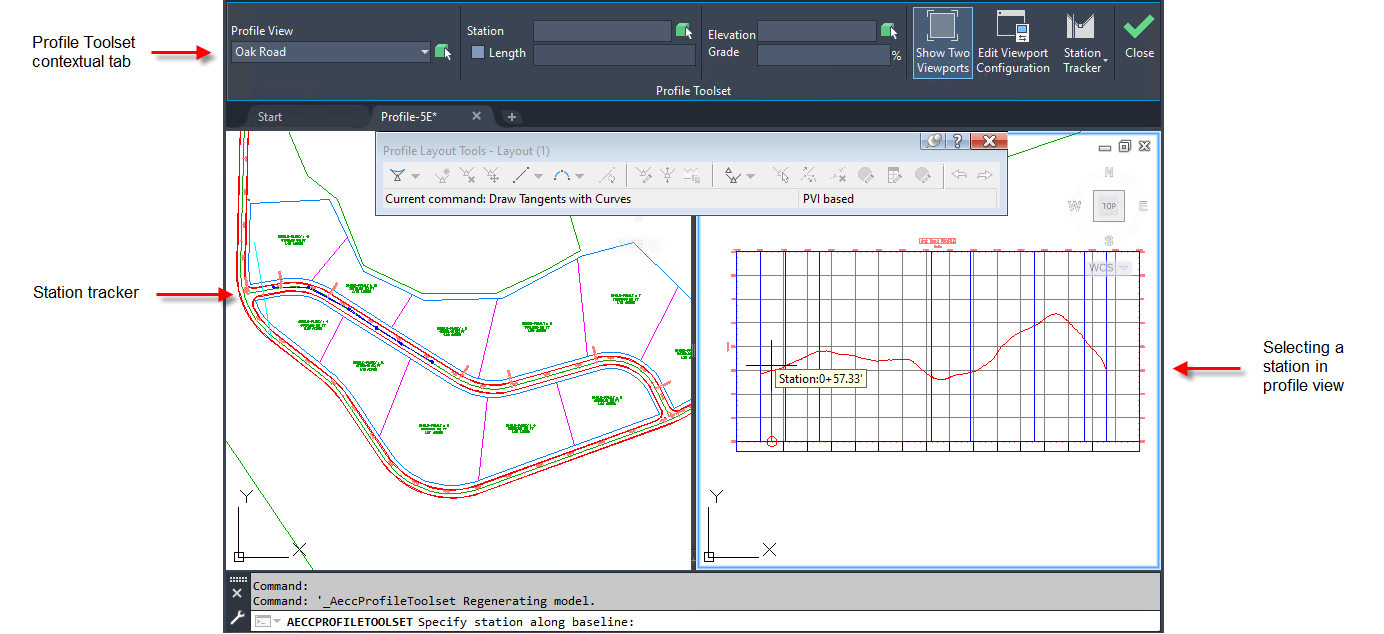
You're first prompted to specify a chainage. You can select a chainage by clicking in either plan view or profile view. You can also enter or change the chainage value in the Chainage field on the ribbon.
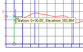
After you specify the chainage, you're prompted for a level. You can move your cursor and click to specify the level.
After you specify the first point using a chainage and level, you can then use the other options on the Profile Toolset tab like Length and Gradient to continue to draw profile entities.
Profile Toolset Contextual Ribbon Tab
When you click the Profile Toolset button on the Transparent ribbon, the Profile Toolset tab is displayed.
- Profile View: Specifies the profile view in which you want to run the transparent command. Use the drop-down list or click
 to select a profile view in the drawing.
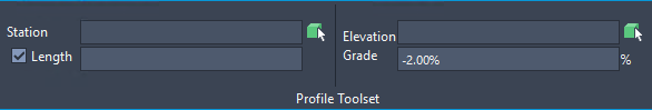
- Chainage: Specifies the chainage to use or displays the chainage that was selected in the drawing. You can edit the chainage and press Tab or Enter to change it. You can also click to select a chainage in either plan or profile view.
Note: When you specify a chainage, you can also specify either a level or a gradient on the Level panel.
- Length check box: When selected, enables the Length field.
Note: When you select the Length check box, you can specify a length in the Length field and you can also specify a gradient in the Gradient field. The Chainage and Level fields become unavailable.
- Length: Specifies the length to use. Use along with a specified gradient to create a VIP at a specified length and gradient.
- Level: Specifies the level to use or displays the level that was selected in the drawing. You can edit the level and press Tab or Enter to change it. You can also click to select a level in profile view.
- Gradient: Specifies the gradient to use. Use along with a specified length.
- Show Two Viewports: Switches the viewport configuration from two viewports back to a single viewport. When you first open the Profile Toolset ribbon tab, the drawing viewports are configured to display a plan view and a profile view. You can click Show Two Viewports to restore the viewports to their preceding state and back again to two viewports.
- Edit Viewport Configuration: Opens the Viewport Configuration dialogue box which you can use to set up the viewports.
- Chainage Tracker: Provides options for controlling the display of the chainage tracker lines in the viewports. For more information, see To Track Chainages in Alignments, Profiles and Sections.