Use this page of the dialogue box to specify the analysis types to run, the outfall part and the tailwater condition and the rainfall data.
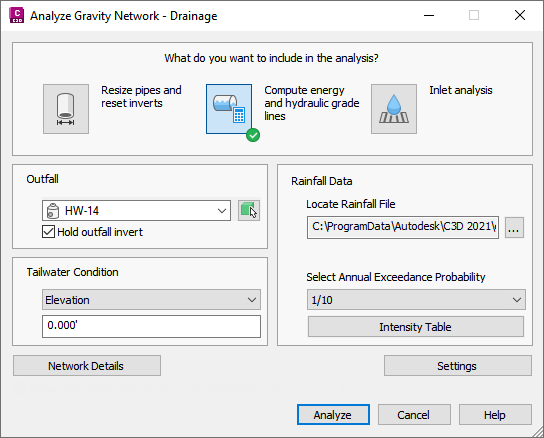

- Analysis Types
-
- Resize Pipes and Reset Inverts: Analyses the flow through the pipes, and then resizes the pipes and resets inverts to accommodate the flow. You have the option to apply these results to the pipe network from the Results page of the dialog box. Applying the results of the analysis will update the pipe sizes and invert levels according to the calculated results, and will apply all of the calculated properties to the pipe network.
Note: This option does not calculate hydraulic properties (EGL and HGL). To calculate hydraulic properties, select the Compute Energy and Hydraulic Gradient Lines analysis type.
- Compute Energy and Hydraulic Gradient Lines: Calculates the energy and hydraulic gradient lines and then reports whether each line in the system is in a normal state, surcharged or flooded. You can display a graphical preview of the results (if a profile view is present in the drawing). You have the option to apply these results to the pipe network from the Results page of the dialog box. Applying the results of the analysis will apply the calculated energy and hydraulic gradient values to the affected parts in the pipe network.
- Inlet Analysis: Analyses the capacity of the inlets and reports the flow, depth and spread at each inlet on the Results page of the dialog box.
- Resize Pipes and Reset Inverts: Analyses the flow through the pipes, and then resizes the pipes and resets inverts to accommodate the flow. You have the option to apply these results to the pipe network from the Results page of the dialog box. Applying the results of the analysis will update the pipe sizes and invert levels according to the calculated results, and will apply all of the calculated properties to the pipe network.
- Outfall
- Specifies the outfall structure or pipe in the pipe network. Select the part from the drop-down list or click
 to select it from the drawing. The following part types are included in this list for selection:
- Structures which have one or more pipes flowing into them, but do not have any pipes flowing away from them.
- Structures which have Outfall specified as their Structure Type on the Part Properties tab of the Structure Properties dialog box.
This list is grayed out if there are no structures or pipes in the drawing which meet the above requirements.
- Hold Outfall Invert
- When selected, specifies that the level at the outfall will be held.
Note: This may cause the levels of the rest of the network to be lowered based on the calculated pipe slopes.
- Tailwater Condition
- Specifies the method in which the depth of tailwater at the outfall part is determined. This provides an initial level value for the performance calculations of the pipe network.
- Level: Specifies a user-defined level for the tailwater depth. Enter the level in the field below the drop-down list.
- (dc + D)/2: Specifies that the tailwater depth is the average of the critical depth and diameter of the pipe that is upstream from the outfall part. The Urban Drainage Design Manual Third Edition, Hydraulic Engineering Circular No. 22 (HEC-22) recommends using this value, unless the tailwater level is known and higher than (dc + D)/2.
- Crown: Specifies that the tailwater depth is assumed to be equal to the crown of the pipe that is upstream from the outfall part.
- Normal Depth: Specifies that the tailwater is assumed to be at normal depth (as determined by Manning's equation).
- Critical Depth: Specifies that the tailwater is assumed to be at critical depth.
Rainfall Data
- Locate Rainfall File
- Specifies the rainfall intensity-duration file to use for the analysis. The following file formats are supported:
- NOAA file (*.csv)
- H&H IDF Tabular file (*.idf)
- X-Degree file (*.csv)
Note: Sample rainfall files are installed to C:\ProgramData\Autodesk\C3D 2024\eng\HHApps\IDF. - Select Annual Exceedance Probability
- Specifies which Annual Exceedance Probability (AEP) to use for analyzing and sizing the pipe network.
The AEP represents the probability of a flood of given magnitude occurring in a given year. For example, 1/10 represents a flood which has a 10% chance of occurring in a given year.
Note: You can select an Annual Exceedance Probability from the drop-down list or by clicking Intensity Table and clicking a row in the table. - Intensity Table
- Opens the Intensity Table page where you can select the AEP by clicking a row in the table.
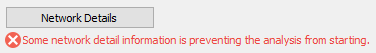
- Network Details
- Opens the Network Details page where you can review and assign values and settings for the pipes and structures associated with the pipe network.
If the analysis type you select cannot be performed, an error message is displayed below the Network Details button.
If some of the network detail information should be reviewed, a warning message is displayed below the Network Details button.
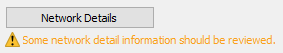
Click the Network Details button to open the Network Details page where you can review errors and warnings and change the network detail settings.
- Settings
- Opens the Settings page where you can specify default settings.
- Analyze
- Runs the analysis and displays the Results page.