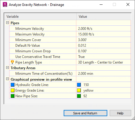
Use this page to specify settings to use for analysing a pipe network.
You can access this dialog box from the General page of the Analyse Gravity Network dialog box.
Pipes
These settings are used in the analysis calculations.
- Minimum Velocity
- Specifies the default minimum velocity of the pipe network.
Minimum Velocity and Maximum Velocity are used during the pipe size analysis. The calculation algorithm is iterative and will check the calculated velocity during different iterations against these values.
- Maximum Velocity
- Specifies the default maximum velocity of the pipe network.
- Minimum Cover
- Specifies the default minimum depth of cover to apply.
This setting is used during the pipe size analysis to assign pipe inverts that meet the minimum cover.
When there is a reference surface, the surface level will be used to calculate the cover value. If there is no reference surface, the structure cover (typically 0) will be used to calculate the cover value.
Note: The minimum cover applies to all pipes except the most downstream pipe (connected to the outfall structure). This may result in the outfall structure appearing above ground when the surface is steeper than the entire pipe network.Note: The minimum cover value as specified on the Settings page is measured down to the (inside) crown of the pipe. It does not take into consideration the thickness of the pipe itself. If you need to account for the thickness of the pipe you can adjust the minimum cover value. The minimum cover values reported on the Results page are reported to the top of the pipe, so those reported values will be approximately equal to the minimum cover value as specified on the Settings page minus the pipe thickness. - Default N-Value
- Specifies the default roughness coefficient (Manning's n) for pipes.
This value is always used in the calculations for pipe size to determine new pipe sizes.
Note: The roughness coefficient assigned directly to each of the pipes is used for calculating EGL and HGL. - Minimum Soffit Drop
- Specifies the level drop between two pipes that are connected by a structure, as measured at the pipe soffits. If the soffit drop that is calculated is less than the specified minimum value, then the specified minimum value will be used.
This setting is used during the pipe size analysis. It's used to set the invert for the downstream pipe, based on the specified drop at the crown of the pipe.
- Use Conservative Travel Time
-
Specifies whether the minimum velocity or the calculated design velocity will be used to calculate the pipe section time if the design velocity is smaller than the minimum velocity.
If the calculated design velocity is larger than the minimum velocity, the design velocity will be used to calculate section time whether Use Conservative Travel Time is set to True or False.
If the design velocity is smaller than the minimum velocity:
- When Use Conservative Travel Time is set to True, the minimum velocity will be used to calculate the pipe section time (pipe length divided by minimum velocity = section time).
- When Use Conservative Travel Time is set to False, the design velocity will be used to calculate the pipe section time (pipe length divided by design velocity = section time).
- Pipe Length Type
-
Specifies the type of pipe length to use for pipe calculations. The selected length will be used to calculate travel time and friction loss. The pipe slope, which is used in the Manning equation for calculations, will always use the relative 2D length of the selected Pipe Length Type. This Pipe Length Type option is not available if Resize Pipes And Reset Inverts is enabled because that analysis always uses the 3D Length – Centre to Centre value.
The available options for Pipe Length Type include the following types that are further described in Part Properties Tab (Pipe Properties Dialog Box):
- 2D Length
- 2D Length - To Inside Edges
- 2D Length - Center to Center
- 3D Length
- 3D Length - To Inside Edges
- 3D Length - Center to Center
Tributary Areas
- Minimum Time of Concentration (Tc)
- Specifies a default minimum value to use for the time of concentration (Tc).
Note: When you create a catchment, the time of concentration is calculated for the catchment and that value is shown on the Network Details page for each catchment. However, if the Tc as calculated for a catchment does not meet the default minimum Tc specified in these settings, an alert icon
 is displayed in the Tc field to inform you that the default value will be used in the calculations.
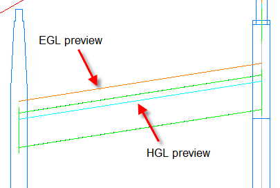
Graphical View in Profile
Use these settings to control the color of the temporary graphics used in profile view to preview the analysis results.
The following illustration shows a detail of the EGL and HGL lines in the preview.
- Hydraulic Gradient Line
- Specifies the colour to use in profile view to indicate the HGL.
- Energy Gradient Line
- Specifies the colour to use in profile view to indicate the EGL.
- New Pipe Size
- Specifies the colour to use in profile view to indicate the updated pipe size.