This rule compares all pipes connected to a single structure and ensures that pipes enter and exit the structure according to the specified drop value.
This rule applies to junction structures only and is intended specifically for gravity-based systems. It is important to note that this rule does not alter the structure in any way, nor does it alter any of the pipes that are connected to the structure. Instead, this rule actually inserts data onto the structure that is read by the pipes when they are using rules. It ensures that the following conditions are achieved when connecting a new pipe to a structure that already has one or more pipes connected to it:
- A pipe exiting a structure is no higher than the lowest pipe entering the structure.
- A pipe entering a structure is no lower than the highest pipe exiting a structure.
- There is always a specified minimum drop distance between the lowest incoming pipe and the highest outgoing pipe.
The drop can be based on a comparison between the soffits, inverts, or centerlines of pipes. A validation check is performed for drops exceeding a certain distance. This determines whether a maximum drop value is violated or whether a drop is required.
Parameters
The following parameters govern the behavior of this rule:
- Drop Reference Location. Specifies the drop location by referencing the pipe’s invert, soffit, or centerline level.
- Drop Value. Specifies the drop value between the lowest incoming pipe and the highest outgoing pipe connected to the structure.
- Maximum Drop Value. Specifies what the maximum drop value is between the lowest incoming pipe and any outgoing pipe connected to the structure. Note that this parameter provides validation only; it does not alter (move or resize) the part in the drawing in any way. It simply produces a rule violation on the part if the specified value is exceeded. This is intended to raise awareness when a drop structure might be needed.
Examples
The following examples show how the Pipe Drop Across Structure rule is applied when a new incoming or outgoing pipe is added to a structure that already has pipes connected to it.
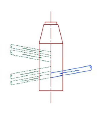
The following illustration shows a junction structure that has two incoming pipes already connected to it on the left side of the structure. When a new incoming pipe is added to the right side of the structure, the pipe cover and gradient rule determines the optimal connection level for the new incoming pipe.
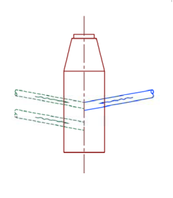
Example 1: Existing Incoming Pipes with New Incoming Pipe
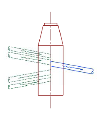
In the following illustration, the junction structure has two incoming pipes already connected to it on the left side of the structure. A new outgoing pipe is added to the right side of the structure. The pipe cover and gradient rule determines the optimal connection level for the new outgoing pipe.
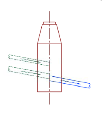
Example 2: Existing Incoming Pipes with New Outgoing Pipe
The following illustration shows a junction structure that has two outgoing pipes already connected to it on the left side of the structure. A new incoming pipe is added to the right side of the structure. The pipe cover and gradient rule determines the optimal connection level for the new incoming pipe.
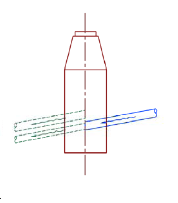
Example 3: Existing Outgoing Pipes with New Incoming Pipe
The following illustration shows a junction structure that has two outgoing pipes already connected to it on the left side of the structure. A new outgoing pipe is added to the right side of the structure. The pipe cover and gradient rule determines the optimal connection level for the new outgoing pipe.
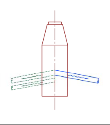
Example 4: Existing Outgoing Pipes with New Outgoing Pipe
The following illustration shows a junction structure that has four pipes already connected to it on the left side of the structure. Two of those pipes are incoming pipes, and the other two are outgoing pipes. A new incoming pipe is added to the right side of the structure. The pipe cover and gradient rule determines the optimal connection level for the new incoming pipe.
Example 5: Existing Incoming and Outgoing Pipes with New Incoming Pipe
The following illustration shows a similar situation with both incoming and outgoing pipes already connected. In this case, a new outgoing pipe is added to the structure. The pipe cover and gradient rule determines the optimal connection level for the new outgoing pipe.
Example 6: Existing Incoming and Outgoing Pipes with New Outgoing Pipe