You can create dynamic offset profiles using the same command you use to create offset alignments. A single default crossfall is specified when you create the offset profiles. After the offset profiles are created, you can assign different crossfall regions to the profiles by modifying the profile properties.
To create dynamic offset profiles
- Use the Create Offset Alignment command and select the Create Profile for Offset Alignment check box on the Create Offset Profile tab.
- Click OK.
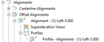
The offset alignments are added to the Offset Alignments collection in Prospector. Offset profiles are created in the Profiles collection inside the named offset alignment collections.
By default the profiles are dynamic and have a single crossfall value. You can add regions for crossfalls or change the update property to static by modifying the offset profile properties.
To modify dynamic offset profiles
- Insert the offset profile into its own profile view. When creating the profile view with the Create Profile View command, select the offset alignment as the alignment on the General page.
Note: Vertical curve geometry of an offset profile appears tessellated in superimposed profile views, so it is recommended to insert the offset profile into its own profile view.
- Select the offset profile in the drawing.
- Right-click and click Offset Profile Properties to display the Profile Properties dialog box.
- Click the Offset Parameters tab and add and edit crossfalls as needed by using the options under
Crossfall Regions.
For more information about how the offset profile geometry is represented, see About Creating Offset Profiles.
Note: You can use crossfall regions for localised crossfall editing. Crossfall regions are not intended to replace superelevation. - Click OK.