You can create dynamic offset profiles using the same command you use to create offset alignments, Create Offset Alignment.
Offset profile geometry
The profile geometry is offset using a default crossfall that you specify. The geometry of the parent profile is replicated in cases where there is a consistent crossfall from the parent profile. You can modify the default crossfall and add slope transition regions using the Offset Parameters tab of the offset profile properties.
Where there is a transition region specified between one crossfall to another crossfall, the offset profile geometry is created as shown in the following example.
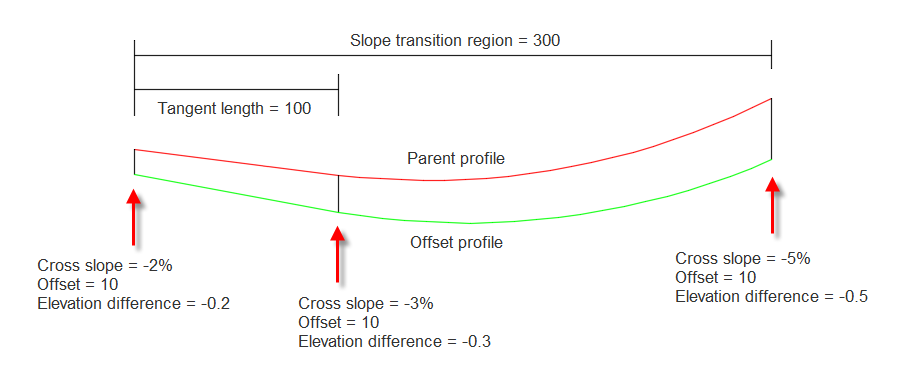
- The level difference values that are shown are between the parent profile and the offset profile and they're determined by the crossfall and the lane width.
- The geometry point is located 1/3 of the way into the transition region, so the crossfall at the geometry point is 1/3 of the total slope transition.
- The offset profile entity will be a straight if the parent profile entity is a straight.
- The offset profile entity will be a parabola if the parent profile entity is a parabola. The offset parabola will use the specified K value for the offset profile (calculated prior to the slope transition being applied).
- The offset profile entity will be a circular curve if the parent profile entity is a circular curve. The offset circular curve will use the specified R value for the offset profile (calculated prior to the slope transition being applied).
- Parabolas and circular curves in the slope transition area will use the K or R of the offset profile curves that was calculated prior to the slope transition being applied.
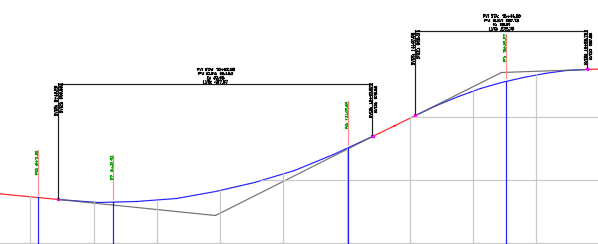
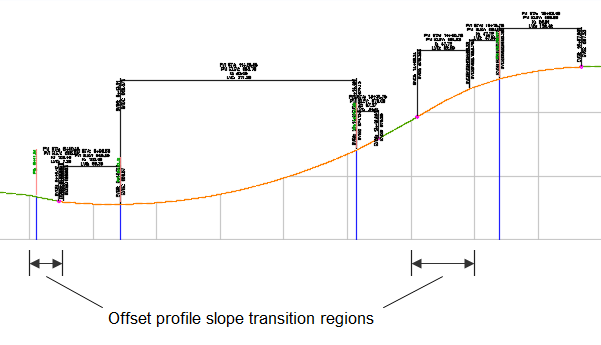
The following examples show a centreline profile (top) and an offset profile with slope transition regions (bottom).
Update mode for offset profiles
Offset profiles are created in a dynamic state by default. A dynamic offset profile automatically updates to reflect changes in the level or geometry of the parent profile and parent alignment. When an offset profile is dynamic, you can add crossfall regions on the Offset Parameters tab, but the profile geometry cannot be edited.
You can change the update mode for an offset profile on the Profile Data tab of the Profile Properties dialog box.