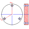
You can create section views from any existing Inventor linked drawing view.
Note: Inventor Link is available only on 64-bit systems, and it is not installed by default.

Before you begin, at least the base view of the part must have been created.
- Click

 . Find
- Draw a cut line in the parent view. The first line segment of the cut line must start outside the part or assembly and end inside the part or assembly. The second line segment must start inside the part or assembly and end outside. Only two line segments are allowed when creating a cut line for an aligned section view.
- Choose the Drawing tab
 New View.
- In the Create Drawing View dialog box,
- View Type: Ortho
- Choose the Section tab.
- Type: Aligned
- Choose OK.
- Select the parent view.
- Specify a location for the orthogonal view, and then press ENTER.
- Select the cut line. The aligned section view is displayed.