Schematic lines are dynamic lines that represent pipes lines or instrument lines. They connect to components, and contain valves and other items. They are similar to AutoCAD lines, but they contain additional information such as flow direction, tag information, and line size. 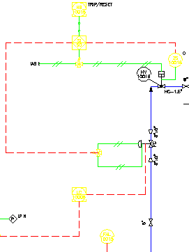
The two types of schematic line groups are pipe lines and instrument lines. Each line type has its own set of properties (such as layer, linetype, thickness, linestyle, color, and tag information).
At the end of each line segment, the arrow indicates the flow direction. The flow direction is determined by the direction you move the line as you create it.
You can change the direction of flow, using the shortcut menu.