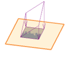
Use the Reference Point tool to create sloped area loads by specifying load values for up to 3 vertices of an area load.

These vertices (reference points) map to the forces F1 through F3 found in the properties of the area load. Forces F2 and F3 are not enabled until the reference points are selected with the Reference Point tool.
This option is available only for non-constrained area loads.
Creating sloped area loads
- Select or create an area load.
- Click Modify | Area Loads tab
 Mode panel
 (Edit Boundary).
- Click Modify | Area Loads > Edit Boundary tab
 Tools panel
 (Reference Point).
Note: Make sure that Structural Loads are turned on in Visibility Graphics.
 - Select the vertices where you would like to specify a load value. Numbers appear that relate to force values in the properties of the load.
Note: Selecting the same point a second time will remove the existing reference at that vertex.
- When you have added enough reference points, click Modify | Area Loads > Edit Boundary tab
 Mode panel
 (Finish Edit Mode).
- Select the area load.
- On the Properties palette, specify force values at each point by entering values in the respective force parameters (F1, F2 or F3). You may specify forces in the x, y, and/or z directions for each reference point.