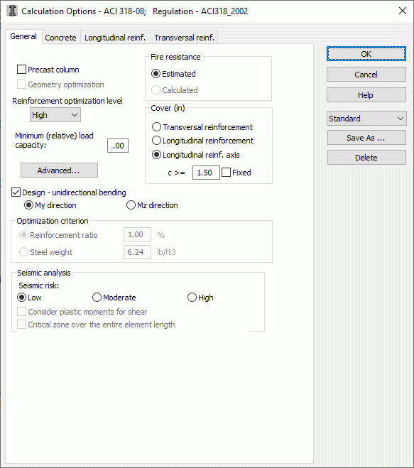
Once the Calculation Options dialog box is opened and the General tab is selected, a dialog box shown below will appear on the screen.

The above dialog box is used to set general column design options:
- Minimum Load Capacity (relative) - Ratio of percentage change (positive or negative) of the minimum load capacity in regard to required loads. If the value is set at 1.2 the load capacity will be increased by at least 20%.Setting the value at 1.0 will result in the column design due to real forces - without increasing the load capacity.A value below 1.0 decreases the load capacity.
- cover
- Lateral Reinforcement - once this option is selected, the cover is set as a distance between the lateral reinforcement surface and the external concrete surface.
- Longitudinal Reinforcement - once this option is selected, the cover is set as a distance between the longitudinal reinforcement surface and the external concrete surface.
- Longitudinal Reinforcement Axis - once this option is selected, the cover is set as a distance between the longitudinal reinforcement axis surface and the external concrete surface.
- c - the minimum reinforcement cover thickness
- Fixed - Once this option is selected, the cover thickness will remain fixed during the calculation process.
Note: The minimum value depends on the required fire rating and the exposure rating. If the Pre-dimensioning option is active the cover value is set automatically in such a way that the minimum requirements are met and the value is still no smaller than the user defined one. Once the 'c' value is fixed the cover thickness value will remain the same during calculations.In case any incompatibility to the exposure rating or the fire rating occurs, the appropriate warning will appear on the screen.
- Precast Column
- calculation of deflection (reinforcement, geometry, deflection)
- advanced
- cracking correction by increasing the reinforcement area (it refers to all the codes except for ACI, BAEL and CSA)
If the dialog box is opened for RC columns, it also includes the option for unidirectional bending. Once the Design - unidirectional bending option is activated, then a column will be designed due to the case of unidirectional bending, independently of moments defined for the other direction. It also refers to ignoring not intended moments, influence of slenderness (second order effects) etc.
Additionally, the General tab for RC columns contains the option for selection of the reinforcement optimization level (high, average, low). For the high optimization level the program searches the greatest number of possible solutions of bar distribution, while for the low level - the lowest possible number. It means that calculations with the high optimization level applied take longer than calculations with the lower level applied, however, the generated reinforcement will be the result of checking a greater number of bar arrangements to find the optimal one. It does not necessarily mean that reinforcement generated for the low optimization level is always less optimal (while for the high level - more optimal than the remaining ones), but a greater number of verified bar arrangements allows finding potentially better solutions. This option is of practical importance only for bars with a considerable number of combinations (take note that the resistance verification has to be performed for each bar arrangement and it proceeds successively for each combination).
See also: RC column design procedure
In the case of the Calculation Options dialog box opened for RC beams, the contents of the General tab depends on a selected RC code. For each of the codes the following parameters can be determined in this dialog box:
- cover dimensions (the options available are identical as those for RC columns)
- c, fixed (the options available are identical as those for RC columns)
- limit value of allowable deflections together with allowable correction of deflection
- switching on the option that allows designing an element as a precast one (precast beam) - the option that enable taking into account in calculations that the beam is precast
- minimum (relative) load capacity
- optimization criteria in the dialog box opened after pressing the Geometry Optimization button
- support depth (the option for precast beams, used to determine the distance from the beam face to the support face)
- additional parameters in the dialog box opened after pressing the Advanced button.
In the case of the Calculation Options dialog box opened for continuous footings, the contents of the General tab depends on a selected RC code. The following parameters may be determined in this dialog box for each code:
- cover size (the same options as for RC columns are available)
- c, fixed (the same options as for RC columns are available)
- minimum load capacity (relative)
- optimization criteria in the dialog box opened after pressing the Geometry Optimization button
- additional parameters in the dialog box opened after pressing the Advanced button
- considering Longitudinal shear which requires defining the minimum ratio of shear capacity to loads.
The Calculation Options (beams or continuous footings) dialog box may contain different options depending on a selected code of RC structure element design:
- French BAEL codes
- American ACI codes
- British BS code
- codes EC2, EC2 (Italian NAD), EC2 (Belgian NAD)
- Canadian code CSA A23.3-94
- code CP65
- Romanian code STAS 10107/0-90
- Italian code DM 9/1/9
- Norwegian code NS 3473: 2003
- Spanish code EHE 99
- Russian code SNiP 2.03.01-84.