Creates and places balloons in the drawing area.
Summary
You can select the parts you want to balloon or automatically create balloons for all non-ballooned parts. You can also renumber and reorganize balloons that exist in the drawing area.
List of Prompts
The following prompts are displayed.
Auto
Creates balloons for specified part references. This option lets you select only the part references that have not been ballooned yet. If you select only one part reference, AutoCAD Mechanical toolset automatically jumps to the “One” command line option.
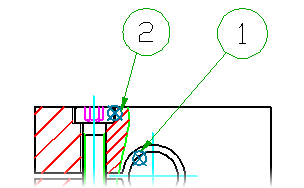
If mechanical structure is not enabled, the balloon leaders start from the center of the part references. If mechanical structure is enabled, the balloon leaders start from the edges of the part or assembly, at the start point of the balloon leader in the preview.
- Select balloon
- Specifies the balloons to rearrange. Press ENTER to end the selection.
- Select point
- Places the balloons as per the preview shown at the cursor. Press SPACE to toggle the preview between horizontal and vertical alignment. Click in the drawing area to place the balloons.
- Angle
- Places the selected balloons along a straight line that is neither horizontal nor vertical.
- First point - Specifies the first point that defines the direction.
- Second point - Specifies the second point that defines the direction.
- Standalone
- Places the selected balloons without a leader, on the part. If you use part references, the balloons are placed on the
 icons. If you use mechanical structure, balloons are placed on the edge of the part or assembly, at the start point of the leader in the preview in the drawing area.
 - Horizontal
- Places the selected balloons along a horizontal straight line.
- Vertical
- Places the selected balloons along a vertical straight line
- Around
- Places the balloons along the sides of a rectangular area.
- Specify first corner - Specifies one corner of the rectangular area.
- Specify other corner - Specifies the diagonally opposite corner of the rectangular area. If the rectangular area you specified is not large enough to contain all the balloons, the command automatically enlarges the rectangular area.
Auto All
Creates balloons for all selected part references, including those that already have balloons attached to them. If you select only one part reference, AutoCAD Mechanical toolset automatically jumps to the “One” command line option.
If mechanical structure is not enabled, the balloon leaders start from the center of the part references. If mechanical structure is enabled, the balloon leaders start from the edges of the part or assembly, at the start point of the balloon leader in the preview.
- Pick object
- Specifies the part references to create balloons for.
Set BOM
Specifies the BOM to set as the current BOM.
To select or create the main BOM, enter M. To select or create a Border BOM, click the corresponding border in model space. To see a list of existing BOMs, enter ?. To create or set the current database to one of the listed BOM databases, type the name of the BOM and press Enter.
Collect
Creates a balloon collection on a single leader.
- Select part reference or balloon
- Specifies the part references or mechanical structure components to create a collected balloon for, or specifies existing balloons to convert to a collected balloon. Press ENTER to proceed to the next prompt.
- Select balloon
- Specifies the balloon leader to collect the balloons on.
- Pick orientation - Selects the orientation of collected balloon. Pick a point to select between horizontal or vertical orientation.
- New
- Collects the balloons under a new leader.
- Start point - Specifies the start point of the balloon leader.
- Next point - Specifies the bend points that define leader segments. Press ENTER to place the balloon at the place you clicked most recently.
- Pick orientation - Selects the orientation of collected balloon. Pick a point to select between horizontal or vertical orientation.
Arrow Inset
Adds an offset to the start point of balloon leaders so that they do not start on the edge of the part. This option is applicable only if you are ballooning mechanical structure components.
Manual
Creates a part reference with a balloon. This option forcibly changes the current BOM to the border BOM that corresponds to the border that the part reference is placed in. If you want the balloon to be based on the main BOM, delete the balloon, set the current BOM to MAIN and balloon the part reference again.
- Point
- Inserts a part reference at the point you specify and displays the Part Reference dialog box. If you place the part reference on an object, the part reference attaches itself to that object.
- Start point - Specifies the start point of the balloon leader.
- Next point - Specifies the bend points that define leader segments. Press ENTER to place the balloon in the drawing area.
- Block
- Creates a part reference for a block reference. If the block has an attribute that has the same name as a component property, the part reference automatically imports its value into the component property.
- Copy
- Creates a complete copy of a part reference, including its data. The new part reference becomes a new BOM item.
- Select part reference - Specifies the part reference to copy.
- Reference
- Creates a part reference that marks an object as another instance of a part that has already been tagged with a part reference. In the BOM, the new part reference increments the quantity of the original part reference instead of adding another row.
- Select part reference - Specifies the part reference you want to add another instance of.
One
Places a single balloon in the drawing area. Unlike with the Auto and Auto all options, you must specify the start point for the balloon leader manually.
Renumber
Renumbers balloons and changes the item numbers of the selected parts in the current BOM.
- Starting item number
- Specifies the number for the first selected balloon.
- Increment
- Specifies the increment value for the next selected balloons.
- Balloon
- Specifies the balloons to renumber, in sequence. Press ENTER to end the selection.
Reorganize
Lines up the balloons horizontally, vertically, in a specified direction, or along the sides of a specified rectangular area. You can also convert the balloons to standalone balloons (balloons without leaders).
- Select balloon
- Specifies the balloons to rearrange. Press ENTER to end the selection.
- Select point
- Places the balloons as per the preview shown at the cursor. Press SPACE to toggle the preview between horizontal and vertical alignment. Click in the drawing area to place the balloons.
- Angle
- Places the selected balloons along a straight line that is neither horizontal nor vertical.
- First point - Specifies the first point that defines the direction.
- Second point - Specifies the second point that defines the direction.
- Standalone
- Places the selected balloons without a leader, on the part. If you use part references, the balloons are placed on the icons. If you use mechanical structure, balloons are placed on the edge of the part or assembly, at the start point of the leader in the preview in the drawing area.
- Horizontal
- Places the selected balloons along a horizontal straight line.
- Vertical
- Places the selected balloons along a vertical straight line
- Around
- Places the balloons along the sides of a rectangular area.
- Specify first corner - Specifies one corner of the rectangular area.
- Specify other corner - Specifies the diagonally opposite corner of the rectangular area. If the rectangular area you specified is not large enough to contain all the balloons, the command automatically enlarges the rectangular area.
Annotation view
Creates balloons for parts and assemblies in an annotation view. When you create balloons for annotation views, AutoCAD Mechanical toolset automatically selects the correct assembly BOM as well as all the components to be ballooned.